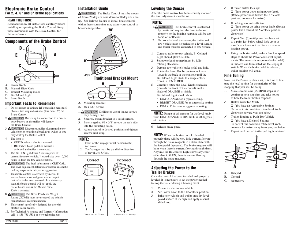
Do not mount or activate rf generating items cell phones two way radios near less than 12 the brake control. Assortment of tekonsha voyager wiring diagram.
Tekonsha Electric Trailer Brake Wiring Diagrams Wiring Diagram
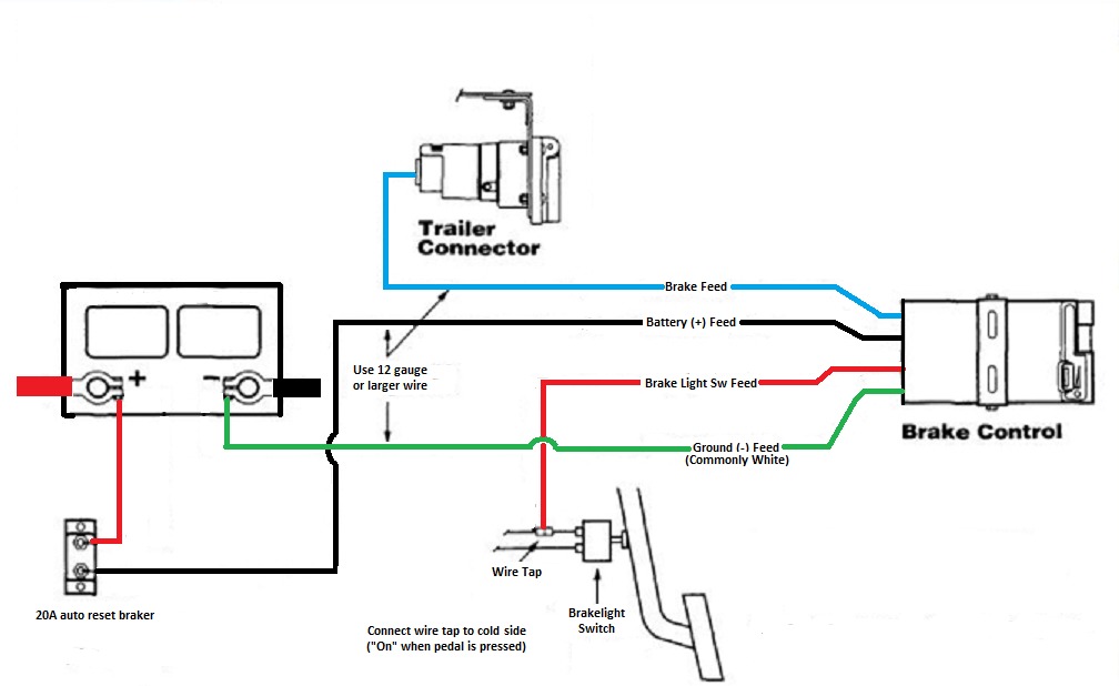
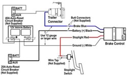
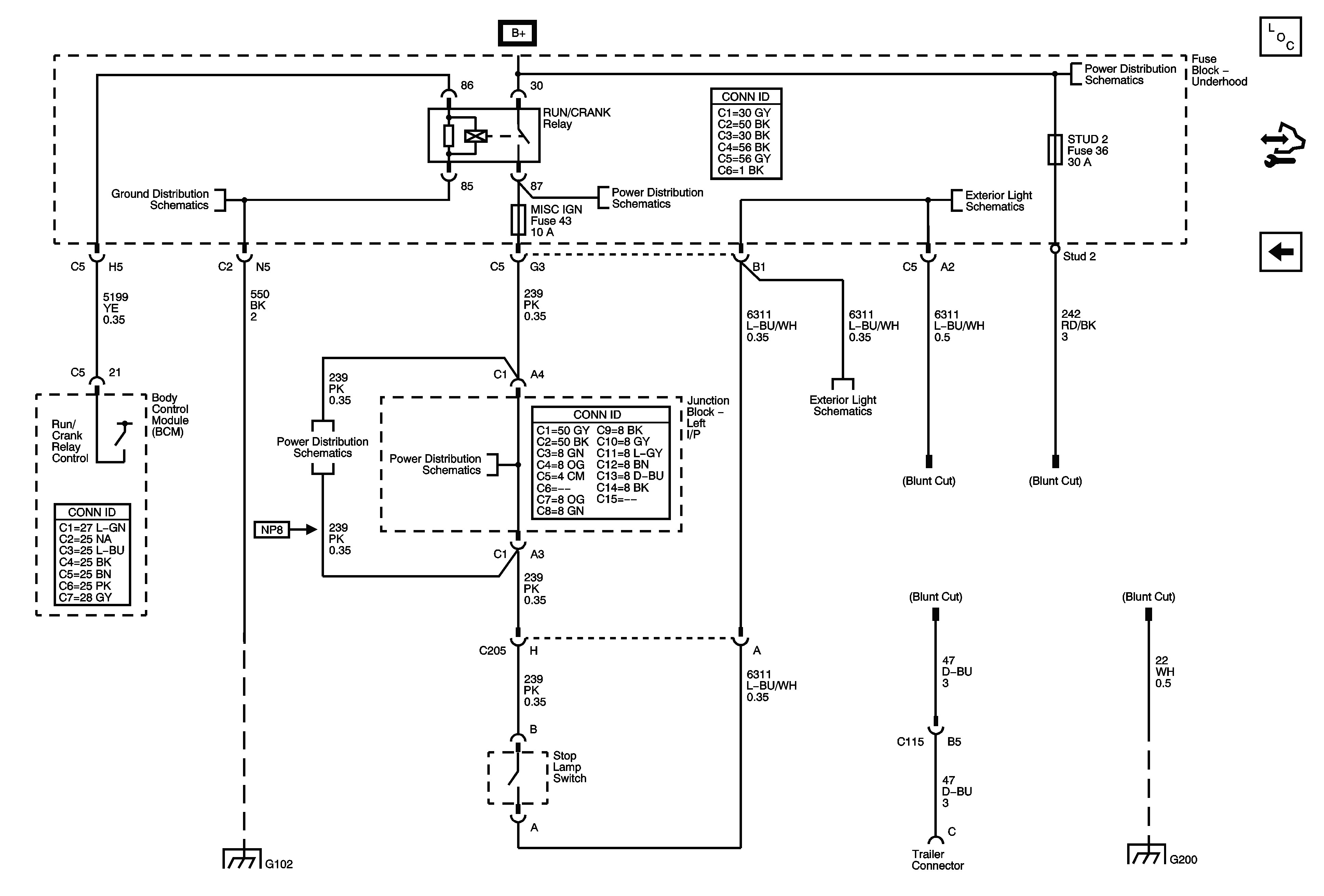
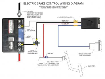
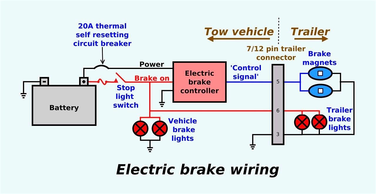
Voyager brake controller wiring diagram. Important facts to remember. You will need a circuit tester like part 40376 to test the wires. A wiring diagram is a streamlined standard pictorial depiction of an electrical circuit. I have attached a basic brake controller wiring diagram for you. The red wire attaches to the brake light switch wire that carriers a signal only when the brake pedal is pressed. I have a 2006 chevy suburban equipted w a trailer package i have the wiring harness to install on to my tekonsha voyager brake controller.
Bracket mounting holes d. I have a tekonsha voyager control and need a copy of the wiring diagram for installation. For 2 4 6 and 8 brake applications. Collection of tekonsha brake controller wiring diagram. Components of the brake control. It shows the parts of the circuit as simplified shapes and the power and signal links in between the gadgets.
The wires coming out of the voyager attach as follows. The problem i have is there are 5 wires on the wiring harness and only 4 on the controller. Thank you in advance for your assistance. You will want to make sure that you ground the white wire to the negative post on the battery. The black wire on the brake controller is the 12 volt hot lead. Tekonsha brake controller wiring diagram wiring diagram for trailer brake controller best tekonsha voyager wiring diagram for trailer brake controller 9030.
Gallery of Voyager Brake Controller Wiring Diagram