Otherwise the structure wont work as it ought to be. Rmd creations 14634 views.
D1bf Mercruiser 3 0 Temp Wiring Diagram Hecho Wiring Library
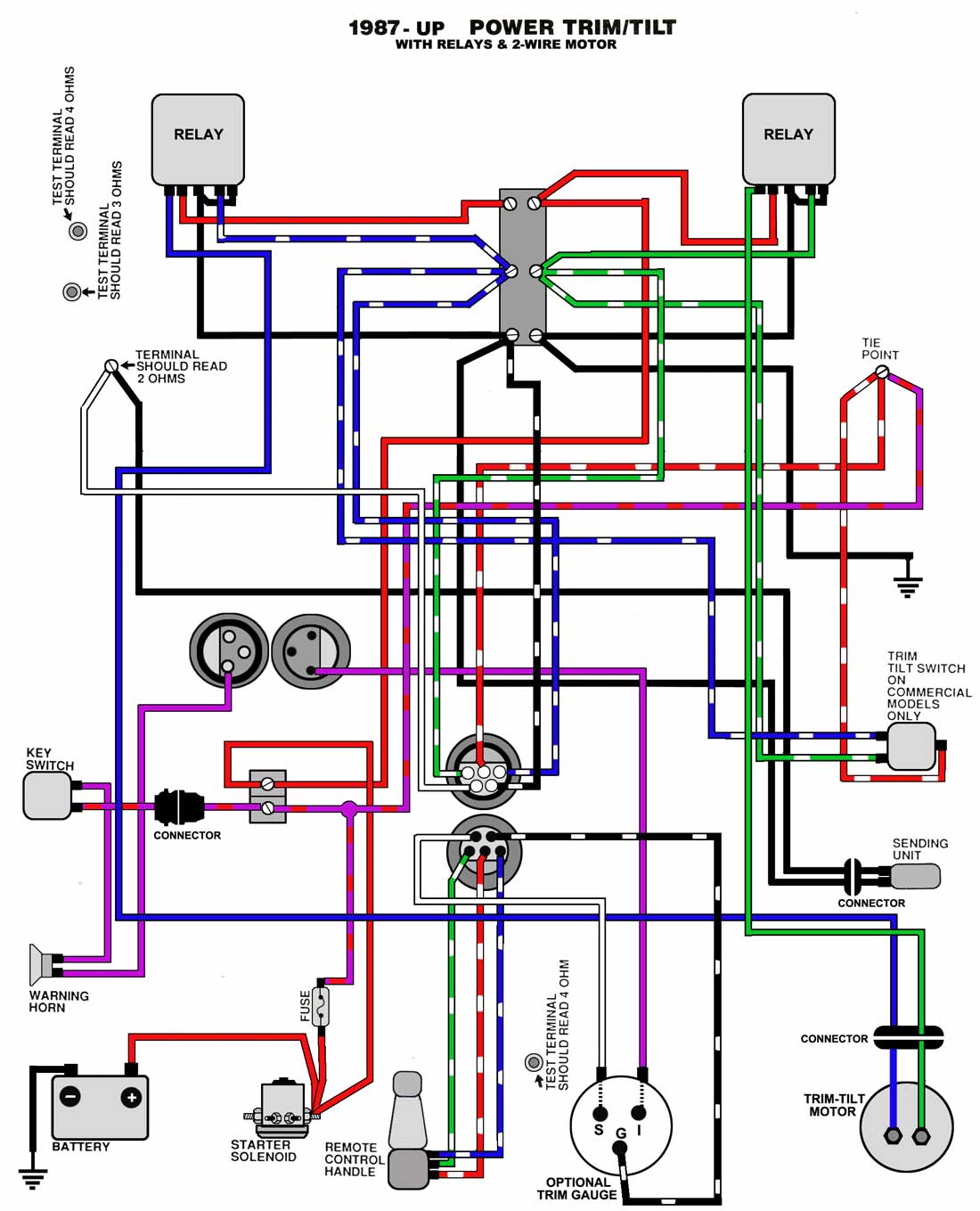
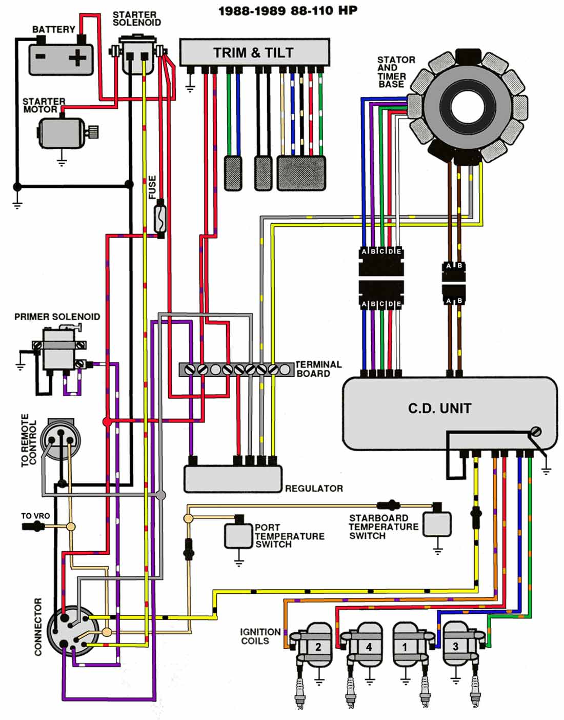
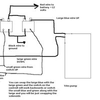
Mercruiser tilt trim wiring diagram. Mercruiser trim sender wiring diagram mercruiser alpha one trim sender wiring diagram mercruiser digital trim sender wiring diagram mercruiser trim position sender wiring diagram every electrical arrangement is composed of various different pieces. Mercruiser tilt trim wiring diagram. A wiring diagram is a simplified traditional photographic depiction of an electrical circuit. Variety of mercury trim motor wiring diagram. Following the wiring diagram for the mercruiser 25l trim pump single solenoid and i am having the hardest time getting it to work. January 22 2019 april 12 2020.
Dangar marine 217426 views. Power tilt and trim wiring wiring diagram schematic name mercruiser trim sender wiring diagram wiring diagram comes with a number of easy to stick to wiring diagram guidelines. Collections of relay wiring diagram furthermore ge relay wiring diagram moreover ge fm radio antenna wiring diagram car tuning car tuning 1000ma 3mode regulated led driver circuit. It shows the elements of the circuit as simplified forms and the power and signal connections between the tools. Mercruiser trim sender wiring diagram. The trim position tp sender is installed on the opposite starboard side.
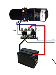
But not again after that. Each part should be placed and connected with different parts in specific way. Mercruiser 120 trim and sensor repair duration. At one point i had it wired and pushed the button and i heard a click. Power trim and tilt kit 826729a4 various years rigging parts trim. This switch permits only a limited amount of outward trim travel to provide safe control at high speeds and prevent damage to drive unit or trim cylinder due to lost side support of drive unit.
E commerce shopping is the safest method of shopping right now during the covid 19 situation. Ill attach the photos of what ive done thus far. These instructions will be easy to grasp and implement. Outboard trim tilt relays explained duration. Trim limittrim position sender switches the trim limit tl switch is located on the left side of the gimbal housing. A family day on the lake enjoying the fresh air and sunshine is a perfect way to get out of the house without worrying about social distancing.
A wiring diagram typically provides information regarding the relative setting and also arrangement of gadgets and terminals on the gadgets to assist in structure or servicing the device. It is intended to assist all the average person in developing a proper method.
Gallery of Mercruiser Tilt Trim Wiring Diagram