You may be in a position to understand precisely once the assignments should be accomplished which makes it easier to suit your needs to. Cdi is the most common ignition system in motorcycles and motorbikes.

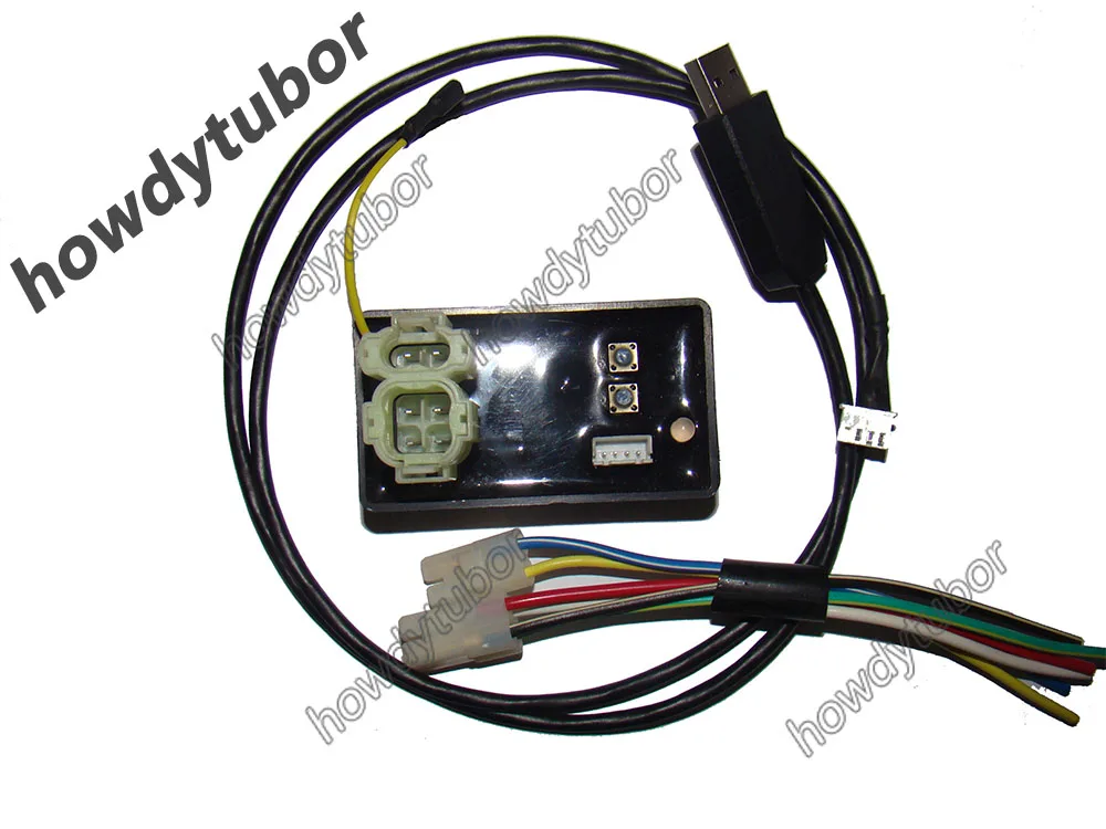
Http Imgs Inkfrog Com Pix Tiandi123 Autd041 2 Jpg
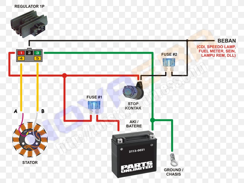
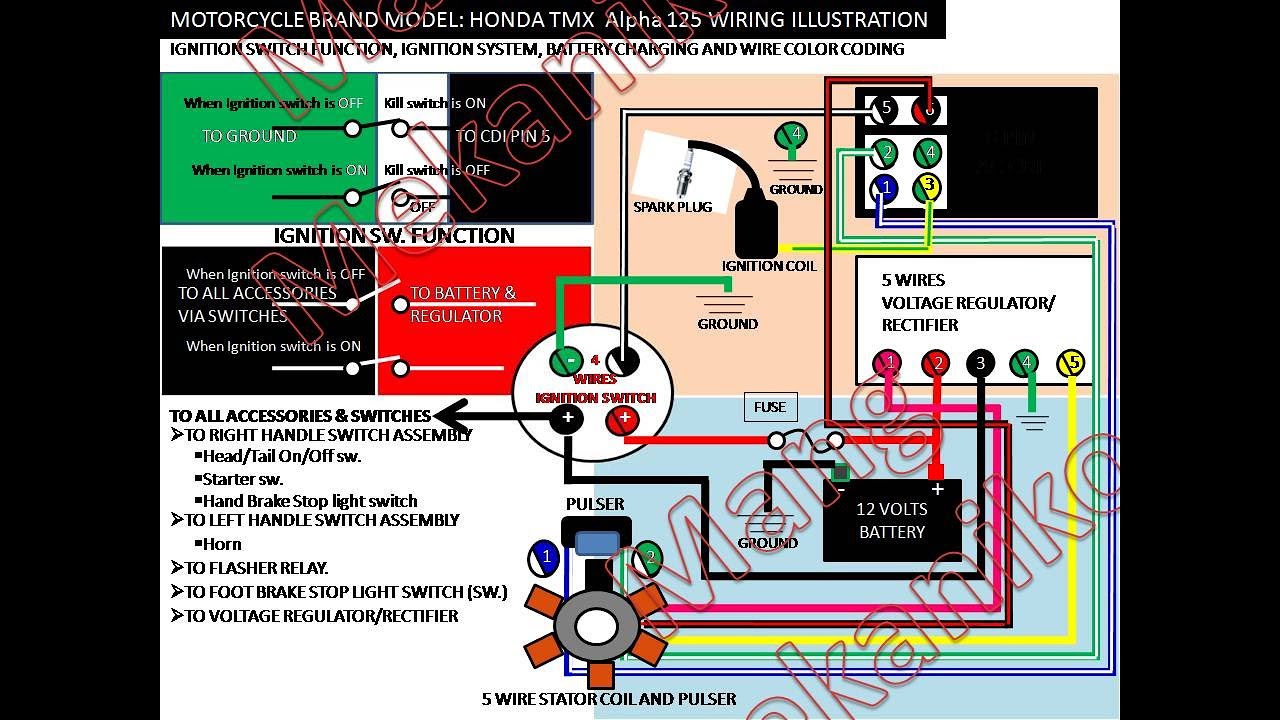
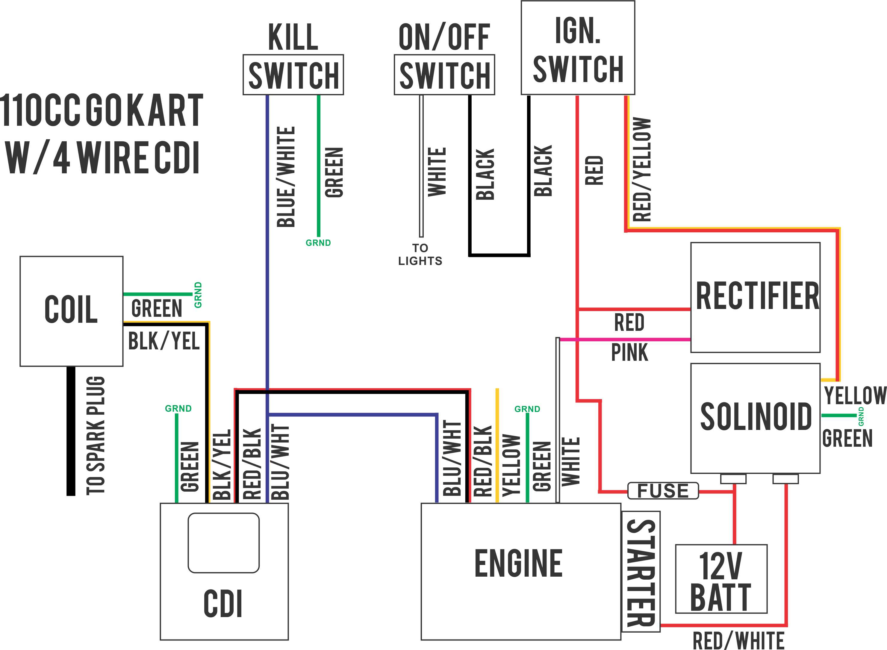
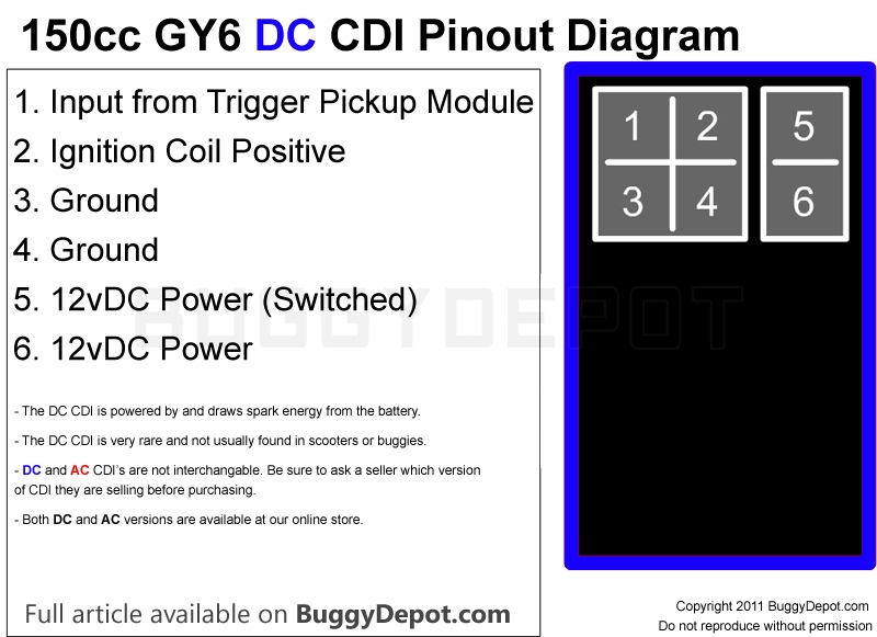
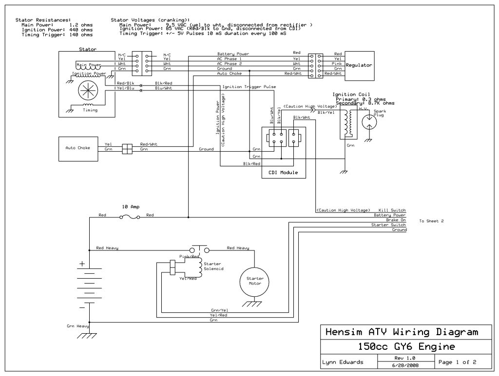
Bike cdi wiring diagram. The input to the cdi unit is derived from two sources of the alternator. In this video i will explain motorcycle or motor bike cdi system in complete detail. Blackred wire to the cdi 1 of the power coils green wire to the frame earth now this is where it differs. You will learn all details to convert a non cdi bike to a. Like all good motorcycle engineers lamberts bikes have produced part specific electrical wiring schematics. For more information on the difference between ac and dc supplied systems check out our cdi unit technical guide how do cdi units work currently under development.
Hope you people may like this. Huge buttons to navigate to lamberts bikes motorcycle cdi wiring diagrams. Provided below is an online pdf document for lamberts bikes 6 pin dc cdi wiring diagram. Now fix the red wire of the kill switch onto the frame by using the top bottle holder screw and the wiring is complete. Weve categorized all our cdi wiring diagrams into ac and dc systems. Each diagram includes the part and associated parts all in one wiring diagram.
You will learn and well understand the cdi system after watching this video. Also while your at it why not cable tie your wires to the frame. In this video i will show you how to wire a cdi in a non cdi bike. Cdi circuit using an scr a few resistors and diodes. Cdi unit wiring diagrams. Referring to the above capacitor discharge ignition circuit diagram we see a simple configuration consisting of a few diodes resistors a scr and a single high voltage capacitor.
I would say blueyellow wire to the cdi this is the wire that tells the cdi when to spark the other wire should be your neutral light you can see this if you remove your sprocket cover and youll see the wire going to the neutral switch. Connect the bluegreen wire from the engine to the bluegreen wire of the cdi unit and then connect the black wire of the engine to the black wire of the cdi unit. Bike generator wiring diagram example of 5 pin cdi box wiring 5 pin cdi box wiring diagram in addition wiring diagram provides you with the time frame in which the tasks are for being completed. Weve even included standard wire colours where appropriate.
Gallery of Bike Cdi Wiring Diagram