Ho we ve r. This section will show you how to get firmware into your controller and run it with basic settings.

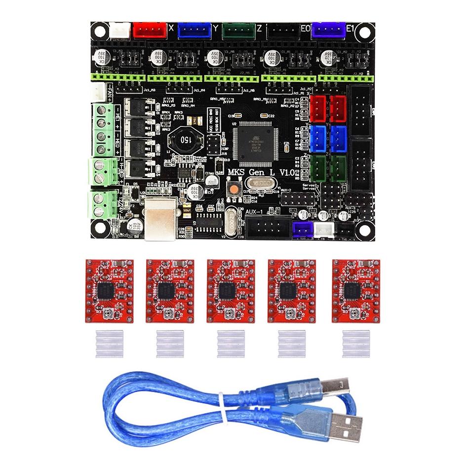
3d Printer Diy Full Kits Mks Gen L Mks Tft 3 2 Touch Screen
Mks gen l wiring diagram. Now there are two fans that connect to a top acrylic plate that mounts to this board and two more fans that connect to the extruder and i am confused on where. Or my 3d printer has an inductive sensor when replacing a conventional proximity sensor with a bltouch. Smoothieboard mks sbase bbp1s alligator azsmz steval 3dp001v1 duet etc. You subsequently have to configure marlin. Wiring the kfb20 is very similar to the ramps 14. This video provides a step by step guide to fitting them to the two most popular mainboards.
Mks gen allows you to connect an external stepper driver mks tb6600 for alls axis. Wiring plan based on available information firmware. Creality3d cr 10s pro wiring. Wiring the makerbase mks gen l v10 board flsun kossel delta 07 17 2017 0940 pm. There was no big surprise since the connection is the same as what teaching tech explained on a mks gen l and the skr 13 wiring diagram is pretty clear. Whenever i bought it i thought press j to jump to the feed.
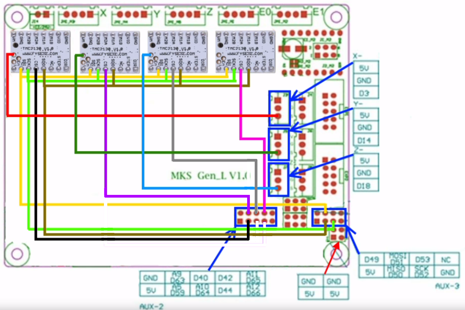
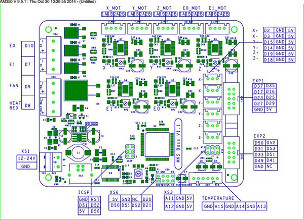
To remember which cable is what i added. Mks gen l v10 tmc2130 drivers wiring for spi and sensor less homing x dia g n o stics y dia g n o stics x cs y cs z cs s d o s c k s d i s s gnd d6 3 d4 0 d4 2 d6 5 5 v d5 9 d6 4 d4 4 d6 6 d4 9 d5 1 d5 3 nc 5 v d5 0 d5 2 gnd aux 2 aux 3 e 0 c s 2. I mention in the instructable that that you either select boardmksgenl or boardramps14efb as the board. Makerbase mkssgenl mks sgenl is a powerful 32 bit 3d printer control board with lpc1768. Press question mark to learn the rest of the keyboard shortcuts. This is the board that came with my flsun kossel delta linear version 3d printer kit.
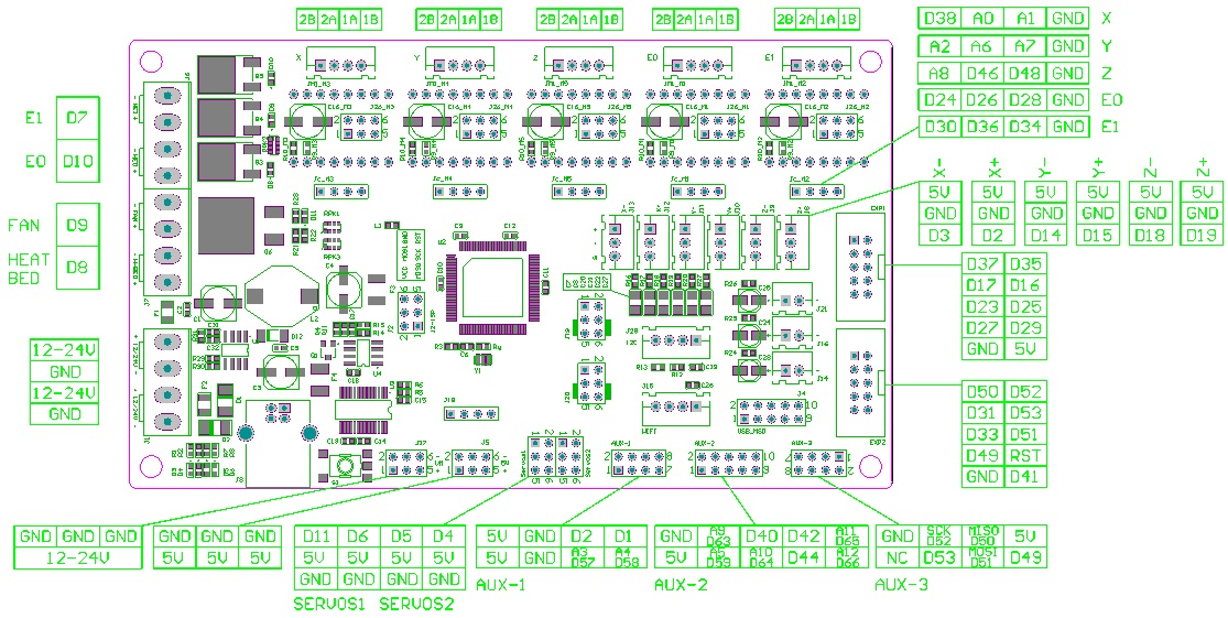
By d e fa u lt ma rlin u se s p ins d5 3 a n d d4 9 for x cs a n d y cs. Most of the pins are connected identical to ramps. Here is a schematic of the mks as well although it is not much use from mks gen circuit and pinoutsmks gen l v tmc drivers wiring for spi and sensor less homing x dia g n o stics y dia g n o stics x cs y cs z cs s d o s c k s d i s s gnd d6 3 d4 0 d4 2 d6 5 5 v d5 9 d6 4 d4 4 d6 6 d4 9 d5 1 d5 3 nc 5 v d5 0 d5 2 gnd aux 2 aux 3 e 0. My board has a large capacity capacitor1 in the end stop input circuit. It covers specifications firmware changes vref wiring and jumper. The mks gen l and the skr v13.
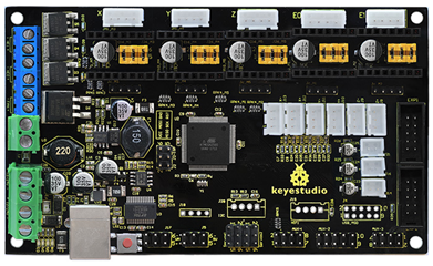
As a matter of fact in the software it is configured as a ramps 14 configuration. No soldering or flying lead is required. Hi folks i am looking for the pcb schematic including the wiring and circuit design of the mks genl v10 board.
Gallery of Mks Gen L Wiring Diagram