In this diagram two 3 way switches control a wall receptacle outlet that may be used to control a lamp from two entrances to a room. A marley ib1 interface box is available to help with connecting the vibration switch to other equipment such as a motor starter or other vfds.

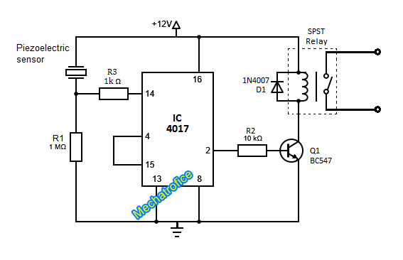
Shock Alarm Circuit
Vibration switch wiring diagram. Refer also to the wiring diagrams of section 8. Wiring ib1 interface box wiring diagram contacts shown in normal state and powered. Three wire cable runs between the switches and the outlet. For an upgrade to velocity ips or mms monitoring or for dual limits ie. Separate alarm and trip setpoints see sw series electronic switches. They are used for applications on machinery or equipment where excessive vibration or shock can damage the equipment or otherwise pose a threat to proper operation.
Depress and hold the reset button for 15 seconds to reset the vibration switch. Some techniques will be. The source is at the sw1 where the hot is connected to. It will allow qualified field technicians to connect vibration sensors in a variety of applications and environments. This circuit is wired the same way as the 3 way lights at this link. Vibration sensor wiring and cabling this technical note describes basic wiring and cabling installation techniques for accelerometers and other vibration sensors.
Unless proper drains andor poured seals are used conduit can allow moisture entry into the switch. 3 way switched outlet wiring. Use good installation practices that slope conduit away from the switch use drains non xp installations only and make. 51 wiring to the vibration switch see terminal numbering legends below. The murphy shock and vibration switches are available in a variety of models. A set of contacts is held in a latched position through a mechanical latch and magnet mechanism.
User wiring diagrams spdt contacts 2 spdt contacts typical installation diagrams cooling tower fan gearbox vibration switch location motor switch location motor heat exchanger fan application note.
Gallery of Vibration Switch Wiring Diagram