If using a two wire 4 20ma temperature or pressure sensor. Shock and vibration switch vs2 series.
Acs880 Cooling Tower Drive Acs880 N5350
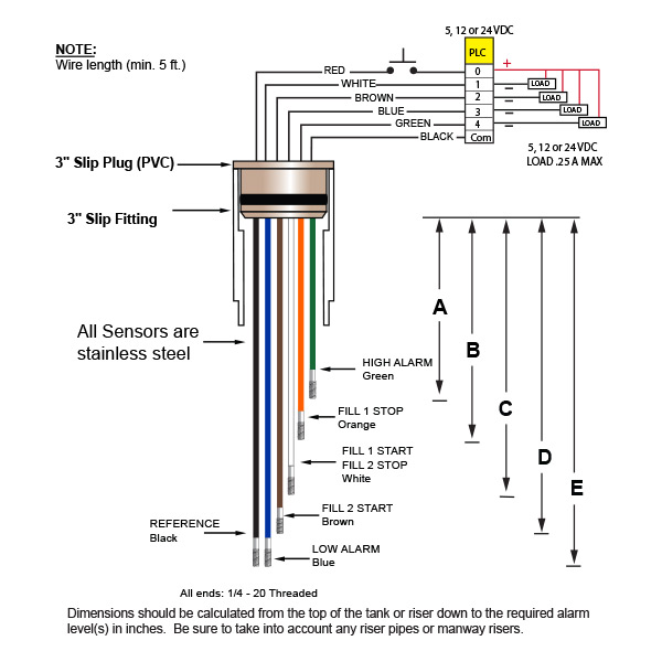
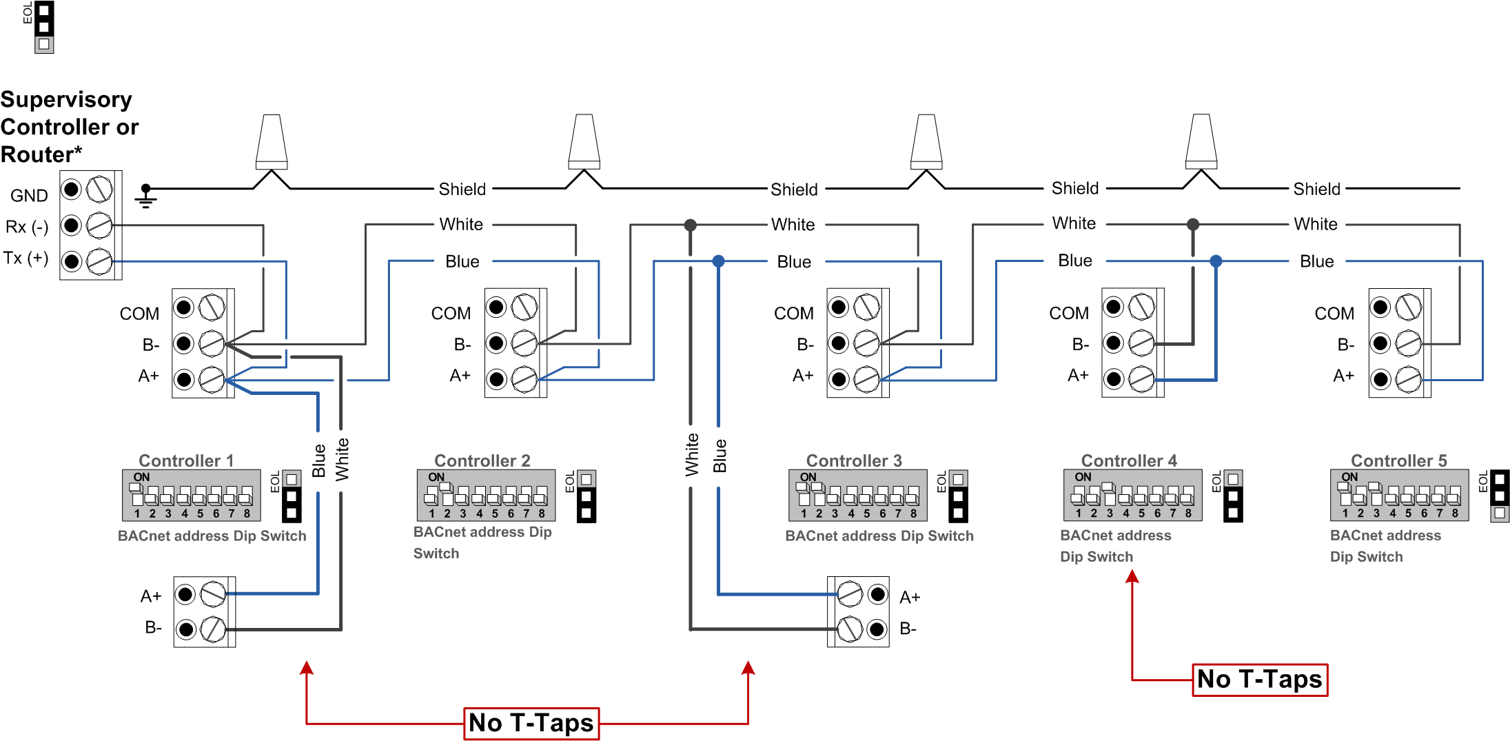
Bac vibration switch wiring diagram. Confirm control wiring from the analog input device into the vfd per chapter 4 of the users manual see appendix d for wiring diagrams. Mechanical operation with multiple options for alarms and reset. 51 wiring to the vibration switch see terminal numbering legends below. Place jumper between opta9 terminals 3 and 5. Featuring wiring diagrams for single pole wall switches commonly used in the home. Then turn the adjustment clockwise a small amount approx.
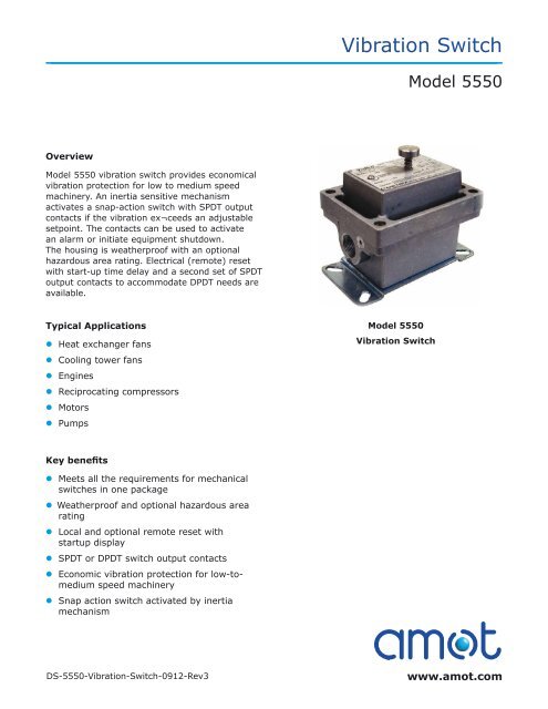
Section 05 pressure and vacuumbook. Reset the switch by depressing the reset plunger and start the machine. Since the switch comes from the factory with the slide switch in the nc position see wiring diagram for the slide switch location the light bulb should turn on immediately. Electronic switches are compatible with building management systems and for use on bac evapco marley and other non bac units. Wire lead to opta9 terminal 4. In this illustration we will going to wire the vibration switch module this module is default off when external vibration force or a movement speed from the sensor a conductive pin will switch on change the electrical property of the sensor when the external force disappears the electrical property will open and turn to off.
Wire lead to opta9 terminal 12. To adjust setpoint when installed on the machine mount and wire the unit. The switch detects excessive fan drive vibration caused by fan icing or any mechanical fault. Vs2exr 24 models with date 0895 and before use old switch. Contact your local bac representative if you do not have this diagram. Refer also to the wiring diagrams of section 8.
Explanation of wiring diagram 1. Unless proper drains andor poured seals are used conduit can allow moisture entry into the switch. When the machine has reached full speed slowly turn the vibration setpoint adjustment counter clockwise until the switch tips. Dated 0 995 after use straight snap switch arm no rollers. Switch wiring shows the power source power in starts at the switch box. Connect a 25 watt light bulb to terminals 2 and 4.
Circuit electrical wiring enters the switch box. Use good installation practices that slope conduit away from the switch use drains non xp installations only and make. How to wire a single switch. Jumper terminals 1 and 3 together. Vcos electronic 110v60hz electric vibration cutout switch with remotelocal reset and delay. To order your vs2 series model use the diagram below.
Guarantees year round reliable and safe operation.
Gallery of Bac Vibration Switch Wiring Diagram