A wide range of molding conditions required for large molded products. 30 sec cycle retains 75 of the maximum injection pressure for 10 sec.

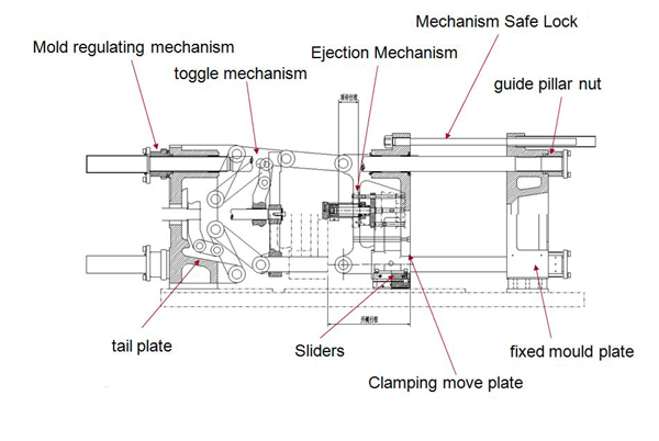
The Composition Appearance And Process Of A Hydraulic
Injection molding machine wiring diagram. When stage 3 is completed the mould closes again. Not even when the controller rex c100 reaches the set temperature i fool the thermocouple with an external heater source really. For example molding is possible without problems under the below harsh conditions. ¾ if the proximity switches are used then use only pnp no type proximity switches. Stage 1 injection followed by stage 2 holding pressure and plasticating and finally stage 3 ejection of the moulded part. A case of wiring done wrong incorrect placement of wires for these components frustrates molders and costs them money to boot.
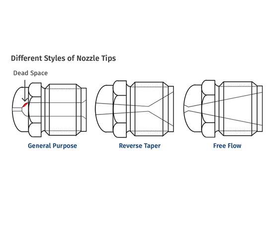
High power 30amp 2 3 5 zone smart series mold wiring. Selecting connectors for a ssh hookup diagram. The connection between the injection moulding machine and the handling device robot is achieved by the plugs specified below. Hey im trying to build a plastic injection molding machine but i cant get the electronics wiring to work please take a look at it and tell me why it isnt working p ive connected a light bulp to represent the band heater and it glows but never turns off. Husky injection molding systems is the worlds largest brand name supplier of injection molding equipment and services to the plastics industry. This shows the wires that supply power and temperature control to the nozzle body and tip.
With one of the broadest product lines in the industry husky equipment is used to manufacture a wide range of plastic products such as bottles and caps for beverages containers for food medical. ¾ the limit switch and solenoids wiring must be done as per given wiring diagram. System consists of three units. Injkon is a complete proven reliable control system for injection molding machine. Take your shop to the next level of productiv ity with the isg and isfd series of hydraulic molding machines from toshiba machine. Energy efficient hydraulics from toshiba machine.
Lpim low pressure injection molding. 1 display unit 2 inputoutput drivers 3 cvt. Blokon 0210 manual page 2 of 24. ¾ the limit switch and solenoids wiring must be done as per given wiring diagram. Smart series mold connector wiring 5 8 12 zone 15amp. For the injection moulding machine see figure 2 and the handling device robot see figure 1 the plug contacts should be capable of taking a minimum of 250 v and 10 a.
Theoretical values retains maximum injection pressure for 5 sec. There are three main stages in the injection moulding cycle. Maximum injection and holding pressure are limited according to molding conditions. 2 vertical injection machine. With clamping capacities ranging from 495. Nozzle heaters thermocouples.
The injection moulding cycle working injection molding diagram. 2015 toshiba machine inc.
Gallery of Injection Molding Machine Wiring Diagram