Do not use aluminum conductors. 2 vav controllervariable air volume vav controller wiring details page 25 power source and loads 26 grounding and isolation 27 io and communication terminals 29 power zone bus and n2 connections 36 analog inputs 36 binary inputs 38 binary outputs 38 analog outputs 38 zone bus 39 wiring to rly50002 relays 39.
Votage Bacnet Wiring Mustanggh May Rmnddesign Nl
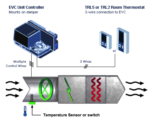
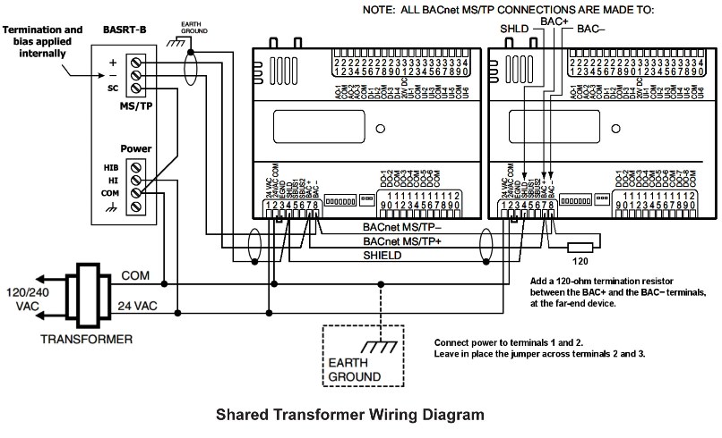
Vav box wiring diagram. Vav ucm 42 installationoperation and maintenance. Mounting and wiring variable air volume modular assembly vma 1400 series controllers technical bulletin 4 key concepts vma position and orientation consider the following when positioning and orienting the vma. If supply connections are for 250 volts or greater all wiring must be insulated for 600v. Model tss terminals provide variable air volume vav control beyond the typical single duct box. They are specifically designed for precise air delivery throughout the entire operating range regardless of the. In many cases a variable air volume box is nothing but an assembly of a sheet metal box with a damper and controls inside a control panel.
Varitrane dvav boxes vxxd andvxxevaritrac. One copy of the document is shipped withvav units that have ucm 42 ddc controllers and is. Mount the vma on a vertical and flat surface where it functions best such as the side of the vav box. 6 vav svx01d en general information overview of manual note. Follow the wiringpiping diagram found on the side of the unit or the inside of the electric heater control panel cover. Supply connections must be made using wires rated for 75c minimum.
Label and wiring diagram is located on the terminal for quick reference during start up. A variable air volume vav box is a part of an hvac system in commercial buildings. Wiring diagrams 58 appendix66. A vav box is integral to the ductwork connecting primary ductwork to secondary ductwork.
Gallery of Vav Box Wiring Diagram