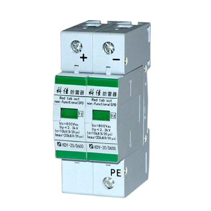
Through the enclosure hole and mount the spd enclosure. The type 2 spd is the main protection system for all low voltage electrical installations.
Surge Protective Devices Spd Schneider Electric Canada
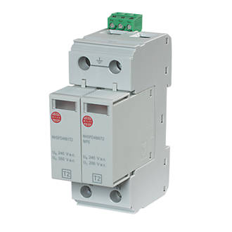
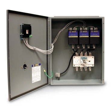
Type 2 spd wiring diagram. Type 1 spd is characterized by a 10350 µs current wave. Nhspd4123t1 2 mod din mounting spd with remote indication contact tn stt single phase supply separate protective earth neutral l1 n pe type 1 lightning arresters nhspd4113t1 2 conductor system. Installed in each electrical switchboard it prevents the spread of overvoltages in the electrical installations and protects the loads. Installed in each electrical switchboard it prevents the spread of overvoltages in the electrical installations and protects the loads. This means that there will be many spds within the installation as there will already be fuses or circuit breakers. Description nhspd4113t1 1 mod din mounting spd with remote indication contact nhspd4133t1 4 conductor system.
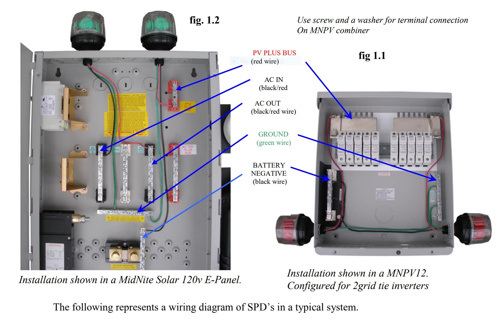
This also follows the lpz or lightning protection zone concept of breaking down. Type s ac 2 speed magnetic starters73 76 class 881073 76 special control circuits75 76 multispeed motor connections76 77 1 phase76 3 phase76 77 programmable lighting controllers78 class 886578 ac lighting contactors79 81. Type 2 spd is characterized by an 820 µs current wave. You must refer to this diagram while wiring the spd. Select the correct wiring diagram for the spd you are install ing. The self inductance l of the connecting wiring is significant 01 uh per foot and.
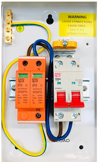
The type 1 spd is with the main incomer the type 2 is with the sub board and the type 3 where you may expect to see a plug top fuse or similar device. Transients have fast rising wave fronts. Spd series type 1 and type 2 units do not require over current protection devices fuses or circuit break ers to operate correctly. Main switch 32a mcb 6mm out the load of the 32a mcb and a 6mm out the n bus bar domestic will be a type 2 spd at the db my interpretations is becuase the total value of the installation will in most if not all cases exceed the cost of what it would cost to install a spd an additional 60 odd quid in materials when installing a new db. Shown this type of diagram is helpful when wiring the. L1 l2 l3 pen list.
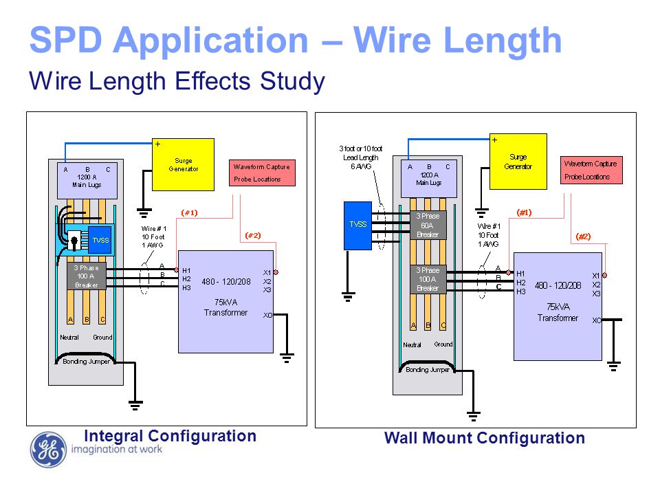
Both the wire size and length used to connect the spd will influence its performance. 1 low speed 2 mid speed 3 high speed green brown diagram ic1 3ø wiring diagrams 1ø wiring diagrams diagram er9 m 3 1 5 9 3 7 11 low speed high speed u1 v1 w1 w2 u2 v2 tk tk thermal overloads two speed stardelta motor switch m 3 0 10v 20v 415v ac 4 20ma outp uts diagram ic2 m 1 240v ac 0 10v outp ut diagram ic3 m 1 0 10v 4 20ma 240v. Typically the rate of rise of the current didt associated with surges can be 100 amps per microsecond or faster. Type 2 spd is characterised by an 820µs current wave. Type 3 protection is required in accordance to 17th edition wiring regulations if cabling distance from a type 1 or 2 spd is greater than 10m or if simply peace of mind that valuable or sensitive equipment need to be protected from surges and damage. The type 2 spd is the main protection system for all low voltage electrical installations.
See figures 9 14. L pen list no.
Gallery of Type 2 Spd Wiring Diagram