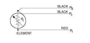
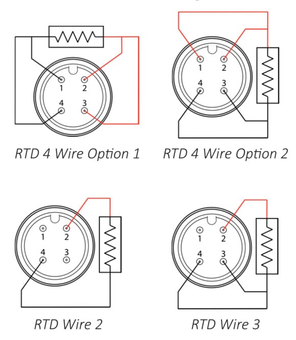
3 wire rtd wiring diagram in this circuit there are three leads coming from the rtd instead of two. Wiring diagram pictures detail.
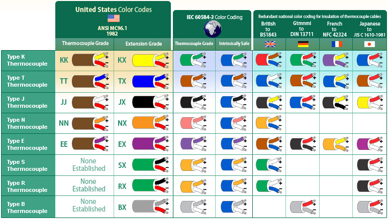
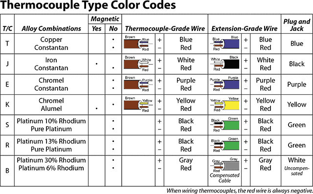
Thermocouple Color Codes Thermocouple Color Coding
Rtd thermocouple wiring diagram. Compact 5000 io analog 4 channel currentvoltagertd thermocouple input module catalog numbers 5069 iy4 5069 iy4k the 5069 iy4 and 5069 iy4k analog 4 channel universal input module offers differential non isolated input channels and thermocouple and. The following connection diagrams illustrate how to connect various rtd types to your daq device. And rt is the rtd. 4 wire rtd signal connection connect each of the red leads on the positive side of the resistive element to the excitation positive and channel positive on the daq device. Eo is the output voltage. Connect the black or white lead on the negative side for the resistive.
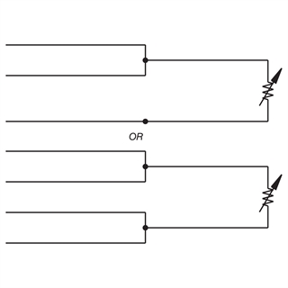
R1 r2 and r3 are fixed resistors. Furthermore thermocouples are designed to be more durable and react faster to changes in temperature because of that same design. How to wire multiple thermocouples to a single instrument through a switch. A thermocouple is composed of two wires made from dissimilar metals. In the united states when youre connecting thermocouple wires to. Rtd wiring configurations there are three types of wire configurations 2 wire 3 wire and 4 wire that are commonly used in rtd sensing circuits.
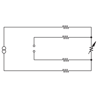
The plot of this equation shows the rtd to be a more linear device than the thermocouple. Point io thermocouple and rtd modules catalog numbers 1734 ir2 1734 ir2e and 1734 it2i user manual. Wiring diagram 10 use a cable tie 12 power the system 12 remove the module 12. For example the positive conductor of a type k thermocouple is made of a chromiumnickel alloy called chromel and the negative conductor is made of an aluminumnickel alloy called alumel. Each wire is made of a specific metal or metal alloy. L1 and l3 carry the measuring current while l2 acts only as a potential lead.
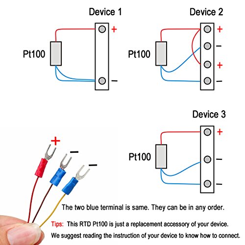
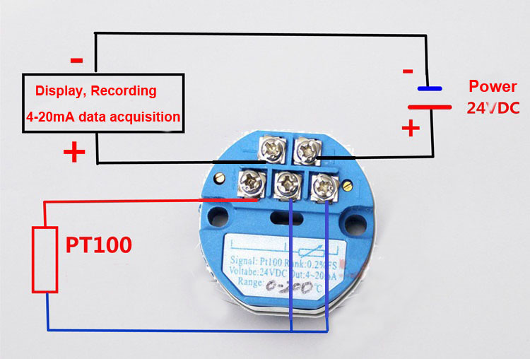
Most thermocouples cost 25 to 3 times less than rtds and although rtd installation is cheaper than thermocouple installation the savings in installation costs are not enough to tip the balance. How to wire one thermocouple to two different receiving instruments. Rtd pt100 3 wire wiring diagram amazon crocsee rtd pt100 temperature sensor probe 3 wires 2m cable thermocouple 58 572f 50 300c 1 2 npt thread industrial scientific. Es is the supply voltage. In this uncompensated circuit lead resistance l1 and l2 add. A 2 wire configuration with a compensating loop is also an option.
Shown is a 2 wire rtd connected to a typical wheatstone bridge circuit. As you can see none of the diagrams are really complicated but there are some rules you need to follow to do it properly. These two wires are joined to form a temperature measurement junction. No current flows through it while the bridge is in balancesince l1 and l3 are in separate arms of the bridgeresistance is canceled. Rtd technical data see also.
Gallery of Rtd Thermocouple Wiring Diagram