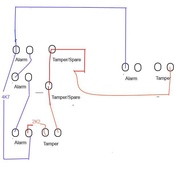
When the switch is open under normal conditions the circuit is incomplete and the siren will not sound. Typically 2 conductor wire is used to wire window.
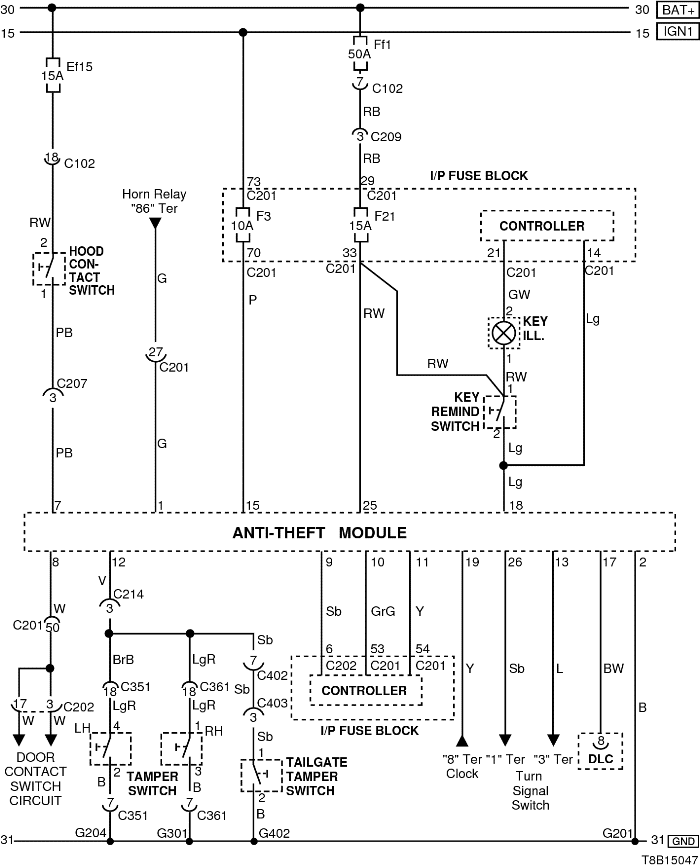
Electrical Wiring Diagram 2009 31 Anti Theft Control System
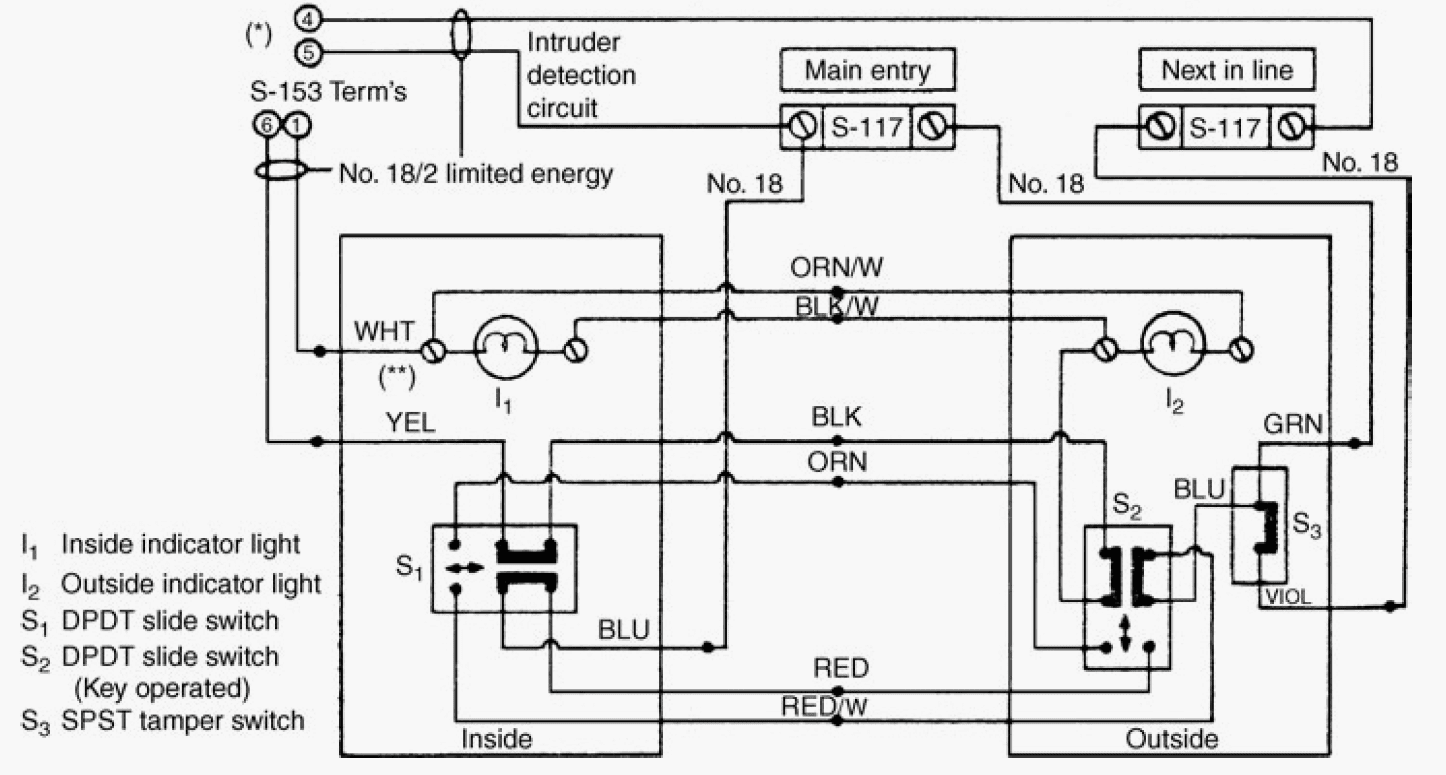
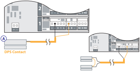
Tamper switch wiring diagram. Tamper switch with idnet iam figure 2 notes. These diagrams show a simplistic version of wiring a sensor. Fire alarm flow switch wiring diagram tamper and flow switch wiring diagrams unique switch symbols wiring diagram ponents. Sprinkler flow switch wiring diagram sprinkler tamper switch wiring diagram download patent ep a2 private generator with automatic transform to. Tamper switch wiring procedure refer to figure 2 and the notes for wiring instructions. Some switches are actually two switches in one these can be used to alert and operate through a regular control unit as well as activate a local visual or audible alarm.
Tamper switch harness and 68k resistor are factory connected to locations 3. Take careful steps to follow the switch wiring diagram as failing to follow them will result in false alarms or render the switch non functional. When the switch is closed then the circuit becomes complete. The cover tamper switch can be wired into the plug circuit or wired as a separate circuit. Field installed wires maintain polarity and use 12 to 18 awg wire from supervised iam assembly to system power supply. See wiring diagrams testing the pts c and its associated protective monitoring system should be tested in accordance with applicable nfpa codes and standards andor the authority having jurisdiction manufacturer recommends quarterly or more frequently.
Tamper proof security system burglar alarm wiring.
Gallery of Tamper Switch Wiring Diagram