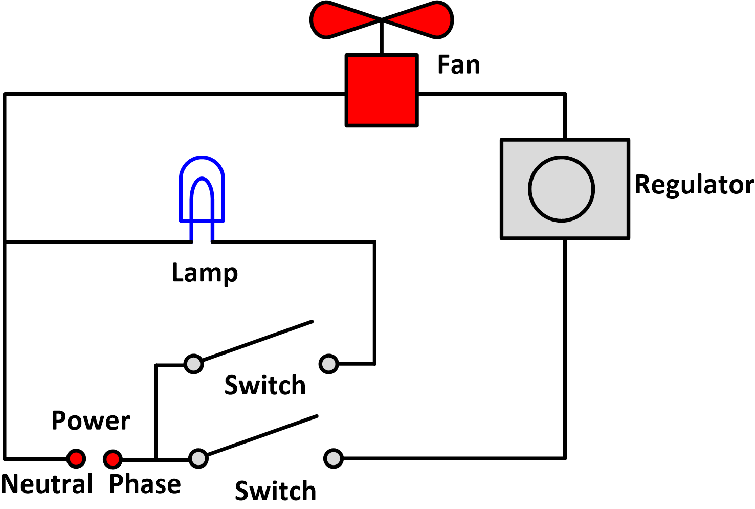
Today we are going to know how fan regulator works fan regulator internal circuit and fan regulator connection diagram. Green wire is for the ground.
Ceiling Fan Wiring Diagram With Capacitor Connection
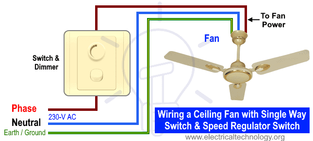
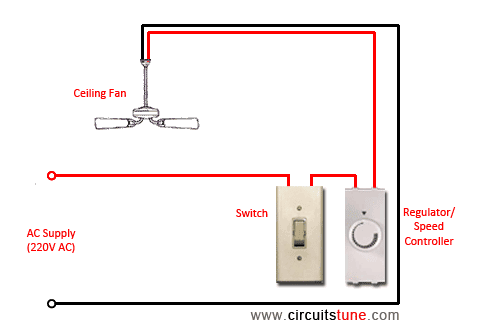
Fan wiring diagram with regulator. Ceiling fan regulator ac motor speed controller circuit diagram. Here a simple spst switch is used to supply power or not to the fan motor and a regulator is used to controlling the fan speed. In this ceiling fan regulator circuit r1500kω is a variable resistor that is used to adjust the fan speed. Its so simple and easy method. Capacitor c1 2a104j is a polyester film capacitor. We are all using the fan regulator in our house with fan.
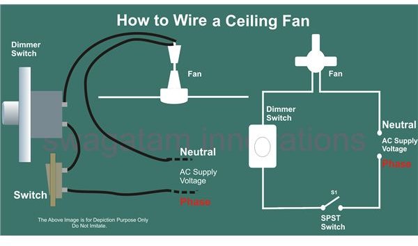
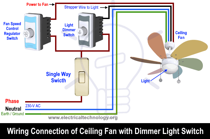
Electric fan relay wiring diagram wiring diagram is a simplified tolerable pictorial representation of an electrical circuitit shows the components of the circuit as simplified shapes and the capability and signal contacts between the devices. Wiring diagram of ceiling fan with regulator. Fan regulator is a device by which we can control the speed of rotation of the fan. Circuit diagram of ceiling fan regulator. Visit the post for more. Fan regulator is a very very much usable electrical or electronic device.
To be noted that the wiring diagram is for ac 220v single phase line with single phase ceiling fan motor. Red wire is sometimes included and acts as a conductor to carry power to the light kit. Blue wire is for the light if light is included with the fan. We will know how conventional fan regulator works internal. Factory service department technical library 40 w 32 is used to describe either white or ivory finish. Fan regulator wiring diagram you old ceiling fan wiring diagram fan regulator circuit ac lamp dimmer mercator ceiling fan sd regulator.
White wire is neutral. This is a simple illustrated circuit diagram of ceiling fan. Foretravel motorhomes repair and technical help. Black wire is for the fan. Though it is very simple but one thing to be noted that switch and regulator should be connected with the phase line of main power not neutral. 3ø wiring diagrams 1ø wiring diagrams diagram er9 m 3 1 5 9 3 7 11 low speed high speed u1 v1 w1 w2 u2 v2 tk tk thermal overloads two speed stardelta motor switch m 3 0 10v 20v 415v ac 4 20ma outp uts diagram ic2 m 1 240v ac 0 10v outp ut diagram ic3 m 1 0 10v 4 20ma 240v ac outp uts these diagrams are current at the time of publication.
In this ceiling fan regulator circuit r1500kw is a variable resistor that is used to adjust the fan speed. Before you begin make sure all electrical circuit breakers related to the wiring are turned off. In this video you will learnt about that how we change fan regulator diagramatically you can see on diagram.
Gallery of Fan Wiring Diagram With Regulator