Potter electric signal company llc st. Thecovertamperswitchcanbewiredintotheplugcircuitorwiredas aseparatecircuitseewiringdiagrams testing theptscanditsassociatedprotectivemonitoringsystemshouldbe.

Language Switch Of A Parity Judgment Task In Multilinguals In
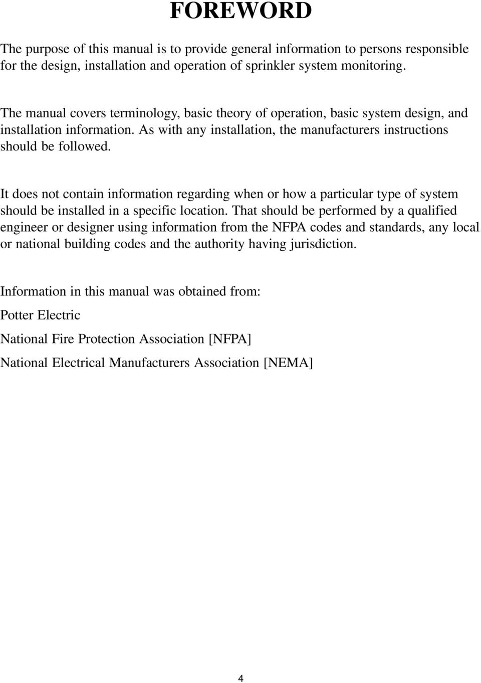
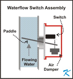
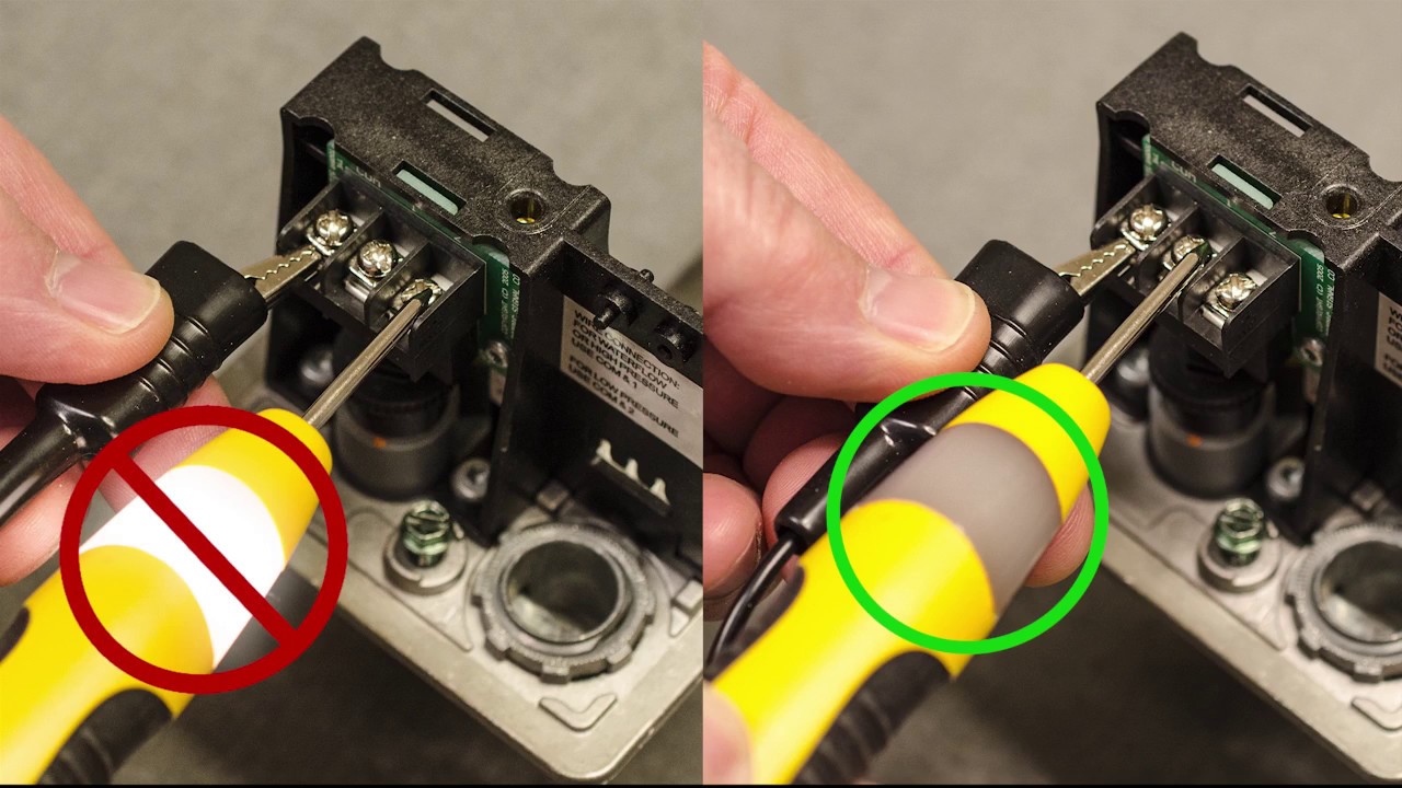
Potter tamper switch wiring diagram. Tamper switch harness and 68k resistor are factory connected to locations 3. An overview of all the new installation features of potters osysu supervisory switch. Field installed wires maintain polarity and use 12 to 18 awg wire from supervised iam assembly to system power supply. Tamper switch with idnet iam figure 2 notes. The cover tamper switch can be wired into the plug circuit or wired as a separate circuit. Louis mo phone.
Cover tamper switch is available as an option which may be used to indicate unauthorized removal of the cover. Nfpa 25 sprinkler tamper switch. Tamper switch wiring procedure refer to figure 2 and the notes for wiring instructions. Cover tamper tamper resistant screws optional cover tamper switch available contact ratings osysu 1. See wiring diagrams testing the pts c and its associated protective monitoring system should be tested in accordance with applicable nfpa codes and standards andor the authority having jurisdiction manufacturer recommends quarterly or more frequently. Wiring both switches from one conduit entrance.
Two sets of spdt form c 100 amps at 125250 vac 20 amps at 30vdc resistive 10 mamps minimum at 24 vdc environmental limitations 40º f to 140ºf 40ºc to 60ºc nema 4x ip 65 and nema 6p ip 67 enclosure. Ul and ulc listed and fm approved dimensions. How to wire a potter ps 10 pressure. See bulletin number. The cover tamper switch can be series wired into this loop or can be wired into a separate normally closed protection circuit see wiring diagrams. One set of spdt form c osysu 2.
525l x 263w x 2d 133cm l x 67cm w x 51cm d with bracket 8 l 203cm weight.
Gallery of Potter Tamper Switch Wiring Diagram