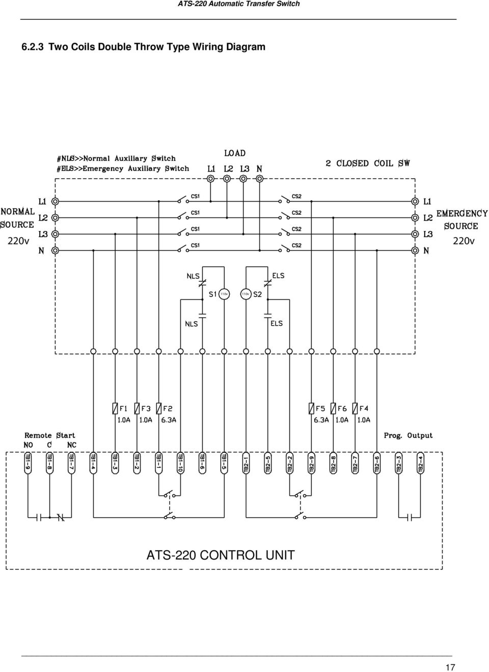
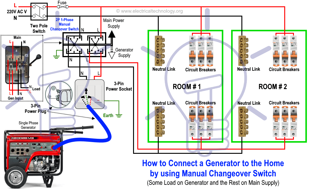
The upper portion of the changeover switch is directly connected to the main power supply while the lower first and right connections slots are connected to the backup power supply like generator or inverter. 1 if the switch controller requires dc power this usually means you will need a second pair of control wires between the switch and the generator to connect to the starting battery.
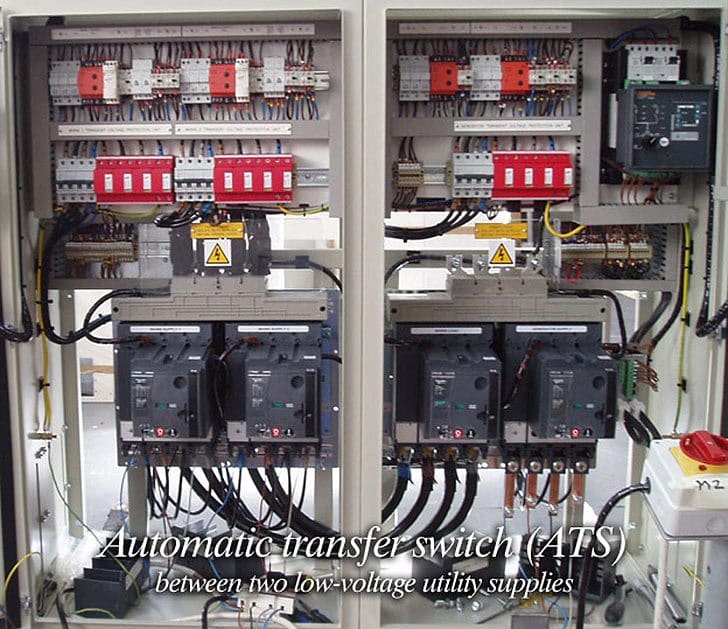
Automatic Transfer Switch Ats Between Two Low Voltage
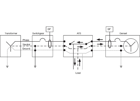
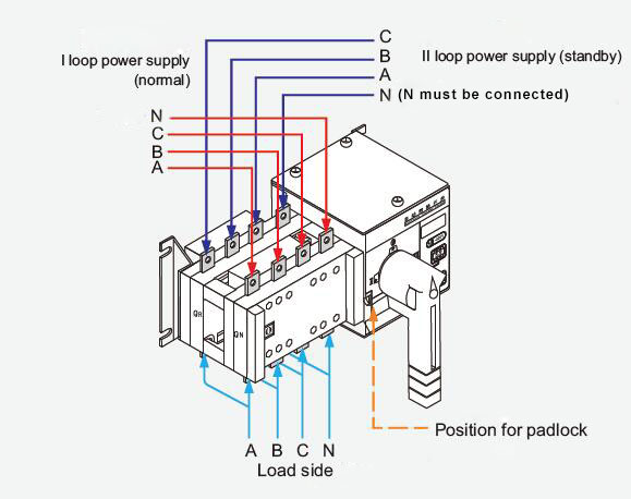
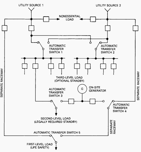
Single phase ats wiring diagram. In this video you will find out how to use phase failure relay in simple auto changeover application. A wiring diagram is a simplified conventional photographic depiction of an electric circuit. 2 these automatic transfer switches and controllers indicated with note 2 can be used with portable generators or rv generators. Interdcnl legal requirements as required by the nec nfpa 101 nfpa 99 and other local state and federal codes and requirements. Wiring diagram asco series 185 automatic transfer switch 100 230 amps frame d single phase 844554. Single line diagrams of emergency and standby power systems with automatic transfer switch ats on photo.
Asco series 185 power transfer switch. In fig 2 different connection and wiring diagrams are shown for a two pole single phase manual changeover switch. The idea of the system is simple. It shows the elements of the circuit as streamlined shapes as well as the power and also signal links between the gadgets. Wiring diagram asco series 300 automatic transfer switch ats 30 230 amps frame d single phase 718516 asco series 30. Asc ts wd 844554 pdf 3993 kb 3993 kb.
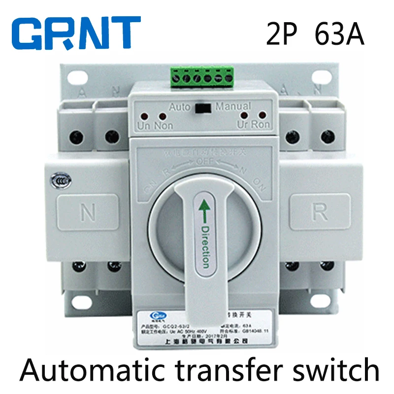
Ats selects between the normal power grid and emergency generator. Variety of ats wiring diagram for standby generator. When there is a power failure on mains 1 the pfr will open.
Gallery of Single Phase Ats Wiring Diagram