Wiring diagrams sometimes called main or construction diagrams show the actual connection points for the wires to the components and terminals of the controller. Kbwc 15l 4l adds dpdt onoff switch 4 wire control model kbwc 25 only.

Motor Repair Supplies Catalog
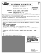
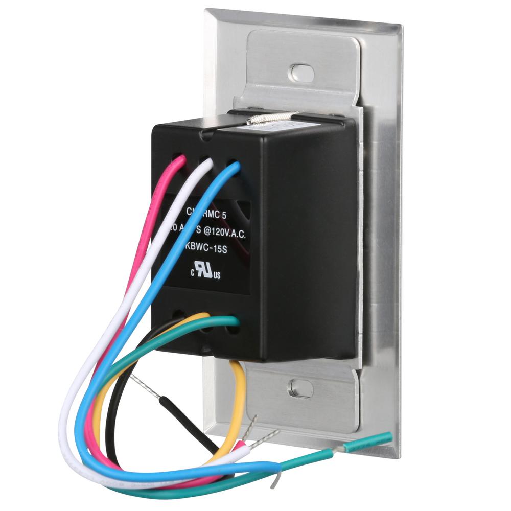
Kbwc 15 wiring diagram. This control must be grounded when installed. Connection diagram for 4 wire controls ground earth g r e e n instructions for installing wall mount speed control u nits h ou ldb e ay q f cr w n electrical code and other local codes which may apply. Basic wiring for motor control technical data. Failure to follow these instructions may result in elec. Supplied standard on all models rated 8 amps and above. 50 out of 5 stars 3.
More buying choices 2841 1 used offer model kbwc 16k ur variable speed fan control. Kbwc 25 4l ns omits onoff switch. More buying choices 1400 2 new offers. Connection diagram for 3 wire controls switch models triac switch black white ac line controlled load auxiliary load l1 l2 ground earth g r e e n r e d black full voltage red red l2 l1 black varialbe voltage 240 volt connection diagram for 4 wire controls ground earth g r e e n instructions for installing wall mount speed control. Kbwc 16c k mounting kit. The kbwc 15k is a distributor packaged solid state ac motor speed fan control.
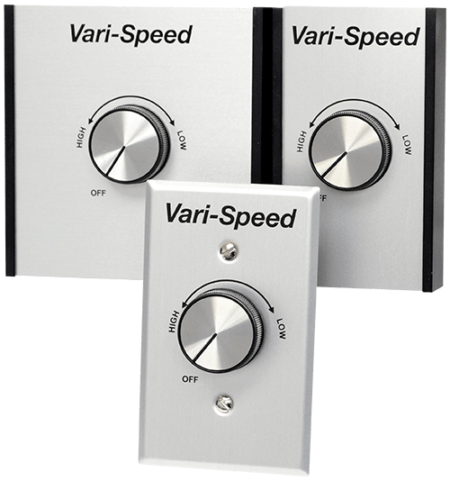
The kbwc 18k is a solid state ac motor fan speed control designed for 2 x 4 electrical wall box installation. Kb electronics kbwc 15 variable speed fan control 120v ac. Kb electronics model kbwc 15k ur variable speed fan control wall mount rated 50 amps at 120 vac for use with shaded pole and psc motors 44 out of 5 stars 40 2157. Connection diagram for 2 wire controls switch models triac switch controlled load ac line connection diagram for no switch model ns 2 wire controls ac line controlled load motor control 38d panel drilling template 1716 sq 1516 58. 4 ohm mono is equivalent to 2 ohm stereo. Includes individual packaging with dial plate knob mounting screws wire connectors and instructions.
The following diagrams are the most popular wiring configurations when using dual voice coil woofers. Check the amplifiers owners manual for minimum impedance the amplifier will handle before hooking up the speakers. It operates from 115 vac 5060 hz and has a maximum rating of 50 amps at 40c. It is designed for mounting in a 2 x 4 electrical wall box. It operates from 115 vac 5060 hz and has a maximum rating of 80 amps at 40âc. Kbwc 15k l adds auxiliary lead 3 wire control.
They show a typical single channel wiring scheme. Wiring diagrams show the connections to the controller.
Gallery of Kbwc 15 Wiring Diagram