A wiring diagram is a streamlined standard pictorial depiction of an electric circuit. Test te rm inal a terminal block b connector d test terminal f switch c control center parts e.
How To Test Wiring In Under 1 Hour
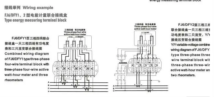
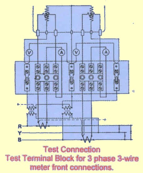
Test terminal block wiring diagram. For example a low power circuit in a car that commands the high. Figure 112 shows a. Type of basic terminal block used for wire to wire connections where the wire feeds through one side and out the other. How to test a four terminal relay. Diagram of contactor for current. Ct test terminal block features continued.
On the opposite side of the terminal block just across from the external wire is the internal screw terminal. Operated metering systems without disrupting load circuit secondary conductors current circuit wiring 4mm² 2voltage circuit wiring 4 mm. It shows the parts of the circuit as simplified shapes and the power as well as signal connections between the gadgets. Collection of terminal block wiring diagram. The external and internal terminals are connected by a bus bar. One for a terminal block.
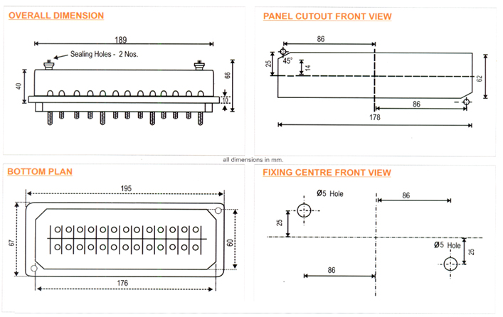
Wire size lightning impulse operating temperature insulation resistance overload capacity d1. Impulse tested at 8kv at an independent test laboratory facilitates easy and safe in situ testing of ct. A terminal block typically is long electrical device that has screw down terminal to land a wire from an external device. Tiers may be bridged creating four common connections. A 4 terminal relay is used so a low power circuit may engage a high power circuit without risk of damage to the low power control circuit. Dual level feed through figure 14 two level feed through in one block.
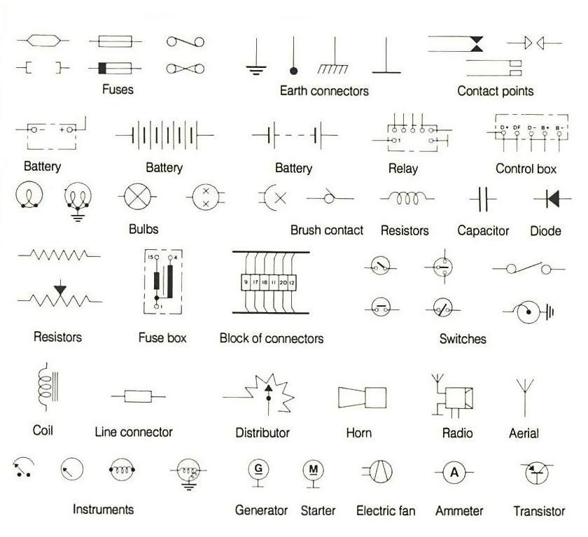
Ledneon indicating lamps diodes and resistors available. B ptt b mr.
Gallery of Test Terminal Block Wiring Diagram