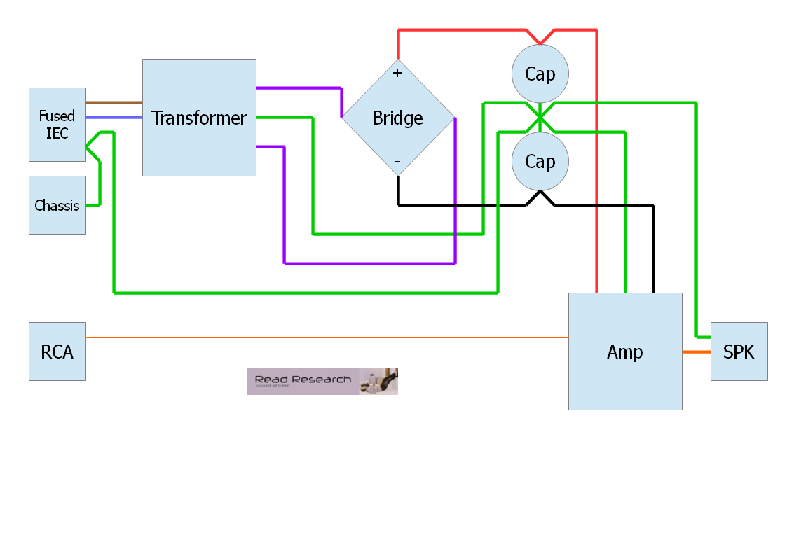
Need help figuering out this wiring diagram for stock radio audio converter i have is an iec auloc bough off ebay a couple months ago but. It shows how a electrical wires are interconnected and may also show where fixtures and components could possibly be attached to the system.
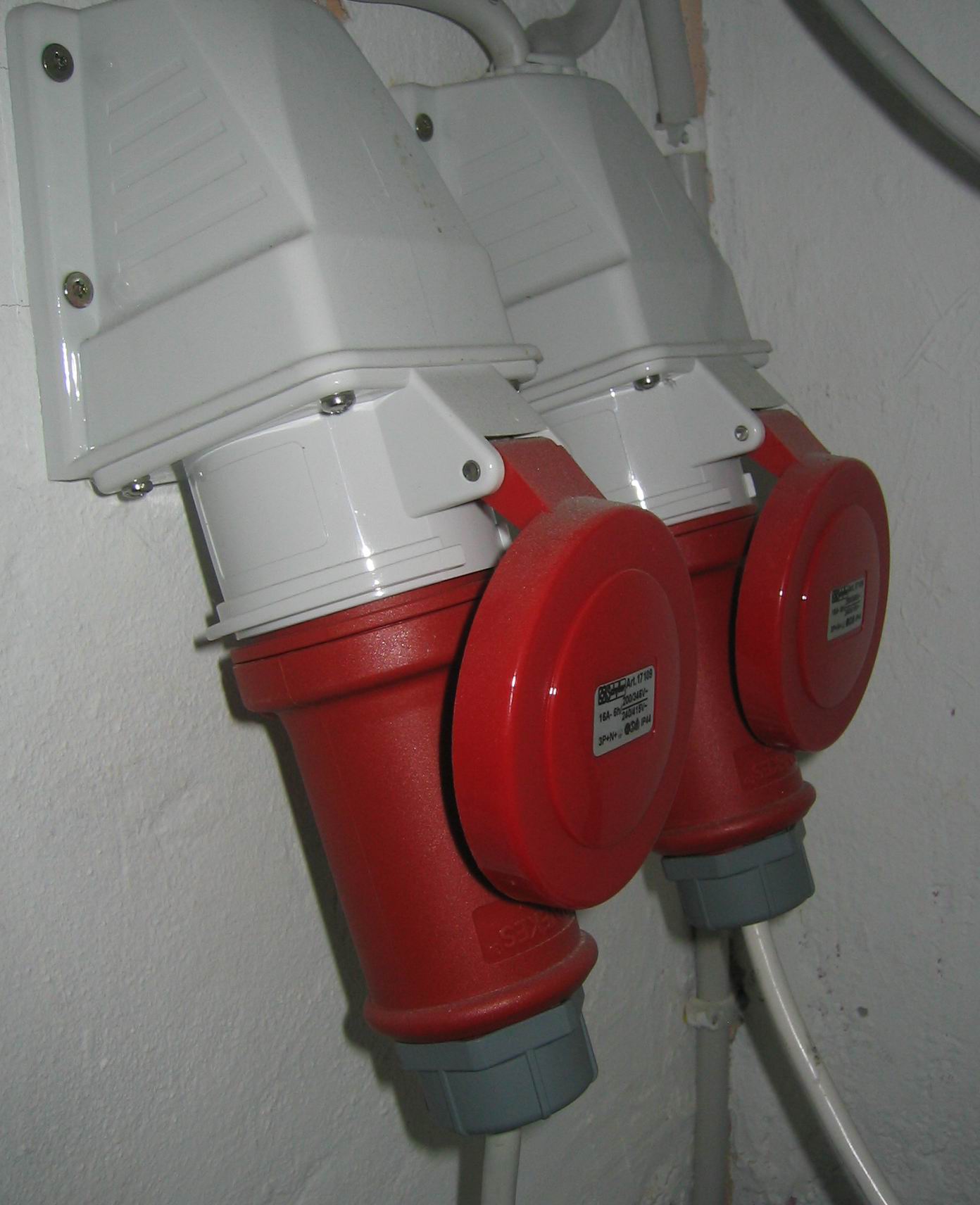
Iec 60309 Wikipedia
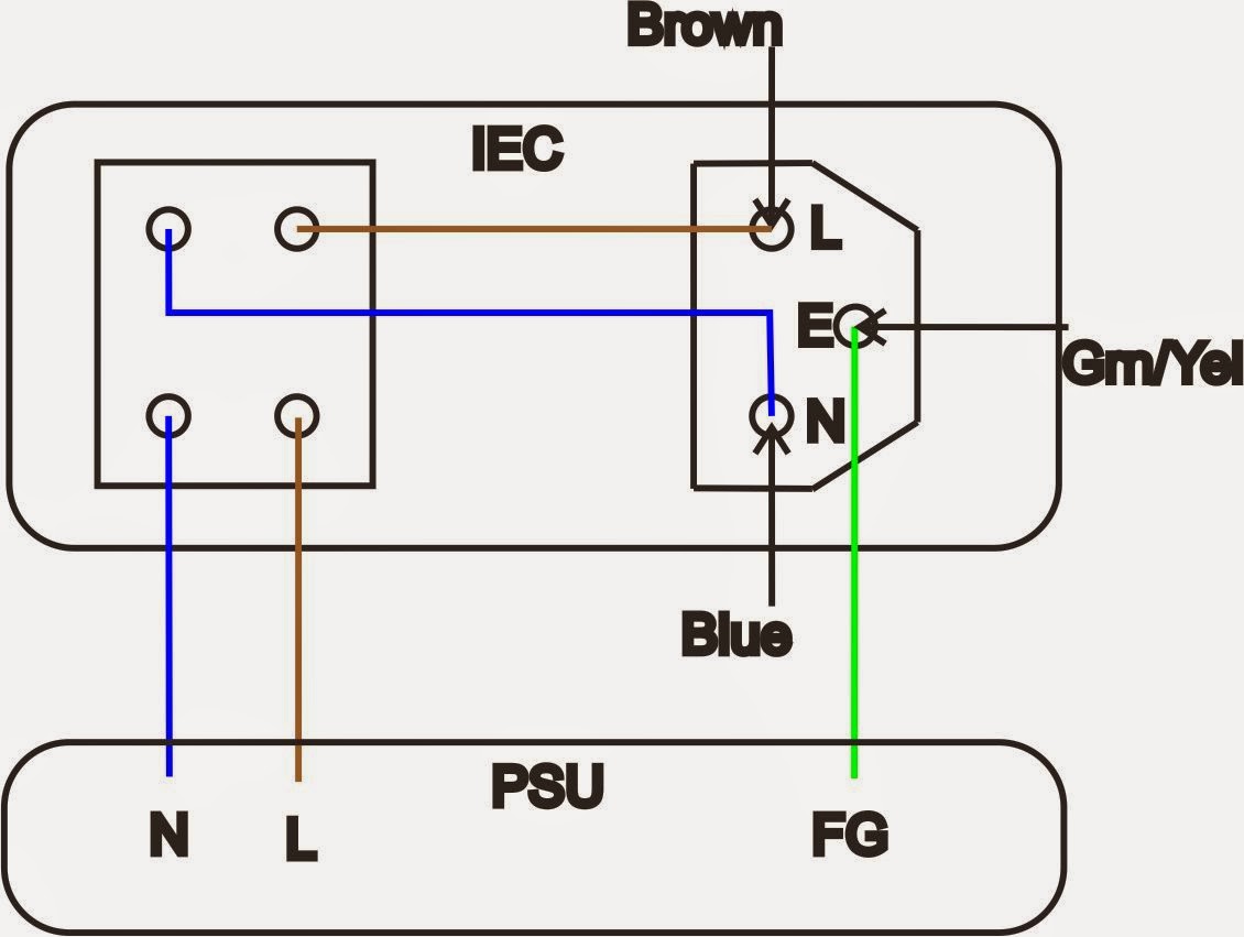
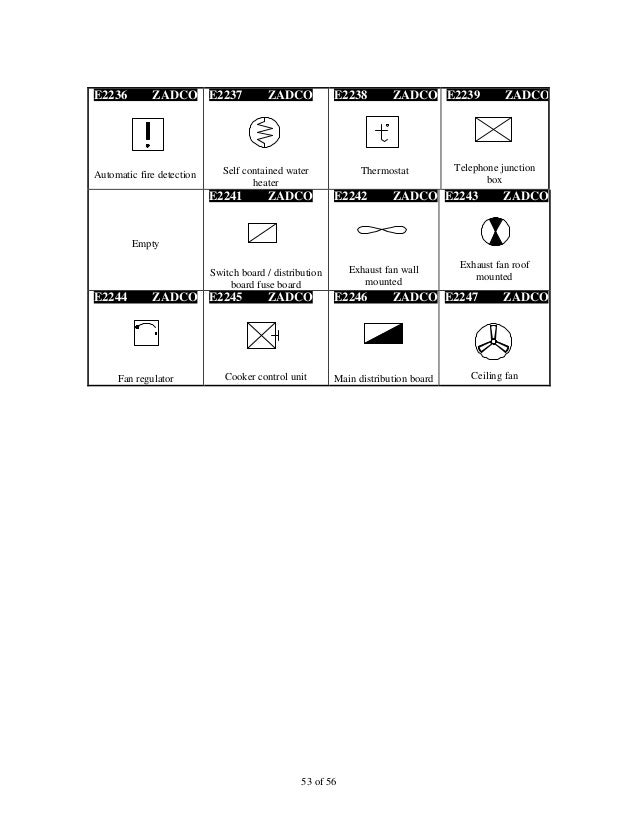
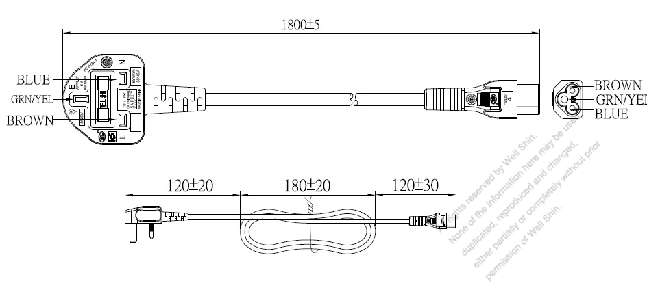
Iec wiring diagram. A wiring diagram is a simplified conventional photographic depiction of an electric circuit. Jun 16 2010 1 hey there. Plug refers to the male connector this being the part with the exposed pins either on the end of a cable or panel mounted. The purpose of this document is to provide a simple cross reference of common schematicwiring diagram symbols used throughout various parts of the world. It shows the elements of the circuit as streamlined forms and the power and signal connections in between the tools. Iec c14 wiring diagram mains inputoutput connector used on most equipment.
Iec schematic diagrams general with the increasing emphasis on globalization many industries are now looking to all parts of the. Start date jun 16 2010. Socket refers to the female part again cable or panel mounted into which the male connector fits. When and how to use a wiring diagram. Included in the iec chart are types of outlets inlet types pin spacing appliance class voltage amperage and more. My question are these.
A wiring diagram is a simple visual representation from the physical connections and physical layout associated with an electrical system or circuit. Connect iec auloc white wire whiteblack to the left speaker output itll come up with a diagram that will tell you which wires do what. The iec chart serves as a guide for proper plug identification. I guess they would be c13 and c14 standard us plugs with the ground pin. Assortment of iec motor starter wiring diagram. What does the.
Im planning on cutting off the male end of a regular power strip and connecting a chassis mount female end.
Gallery of Iec Wiring Diagram