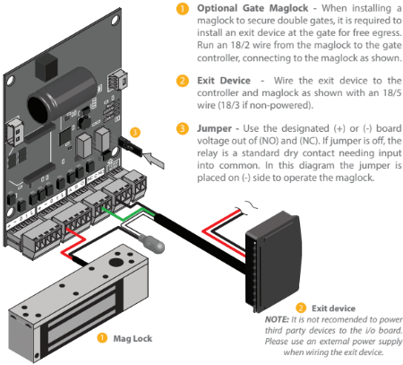
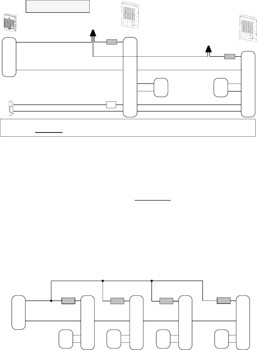
Slide maglock on header plate. The wiring diagrams are shown on page 14 of the installation instructions attached.

Pi Manufacture
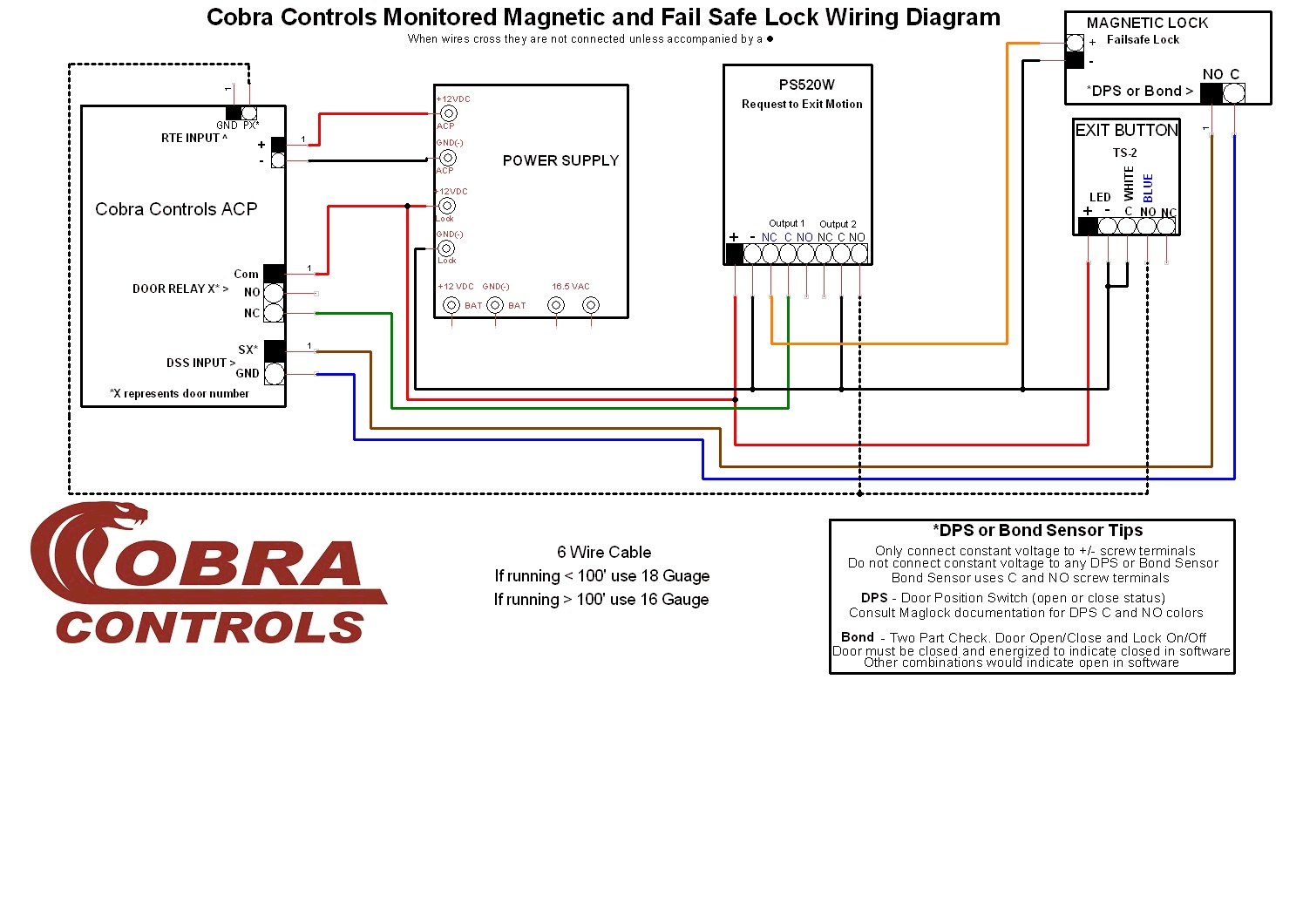
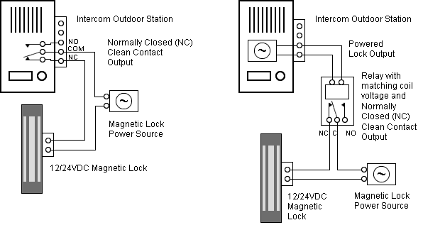
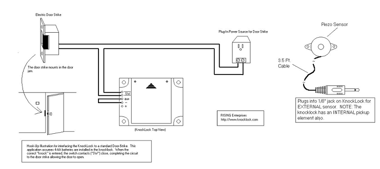
External maglock wiring diagram. Connecting diagram 2c wire leads. Commax double door wiring diagram. Common wiring diagrams. A wiring diagram is a streamlined standard pictorial depiction of an electrical circuit. Wiring diagram for mag lock. It reveals the components of the circuit as simplified forms and also the power and also signal connections between the tools.
Assortment of locknetics maglock wiring diagram. Remove maglock and secure header mounting plate with the six remaining screws. The following reference sections provide installation documents and wiring diagram schematics for maglocks door access system components kits and equipment. Fail secure not working. Wiring instructions magnetic lock or fail safe strike with button keypad maintained button and remote receiver. Single door controlled egress wiring diagram 01 single door digital entry wiring diagram 10 single door dk 26 with door prop alarm wiring diagram 15 single door dk1 11 xms dt 7 wiring diagram 20 single door dk 26 remote release wiring diagram 14 single door dk 26 unl 24 and dt 7 wiring diagram 18 single door dk 26 using the hard code to toggle lock off and on wiring diagram.
Adjust the position of maglock to contact the armature. It shows the components of the circuit as simplified shapes and also the power as well as signal connections in between the gadgets. Monitoring output dual voltage and 4 3 lz 150 z 150 lz bracket z bracket application application x value x value lz 750 z 750 lz 01st lz gl600 z gl600 10003s 37mm 10003f 32mm 48mm 44mm 48mm 45mm 48mm 62mm lz 600. 1224v dc surface mount external magnetic lock gl1200 monitored with male conduit thread holding force. Slide maglock on header mounting plate. This magnetic lock will operate via 12v dc or 24v dc however please ensure you check the wiring connections correctly for use with a 12v dc power supply or 24v power supply before you turn the power on.
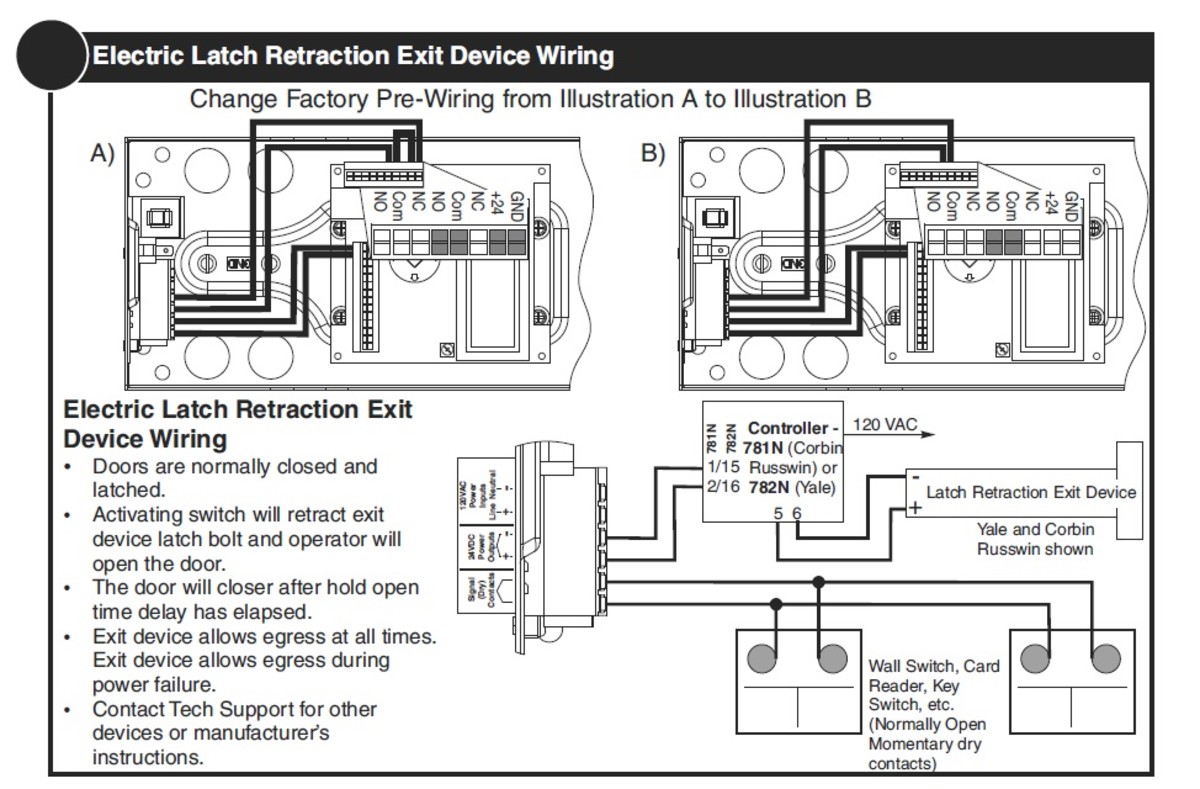
Fail secure not working. Chexit with electric strike and auto operator. El wiring schematic. Dual voltage 5c wire leads. Common wiring diagrams. Wired in series power supply for fail safe strikes and magnetic locks should be dc.
If you have additional questions regarding hardware or software requirements or the wiring diagram set up we are available to help. Monitoring output 6c wire leads. This will conver t the ac to dc. Single voltage input 4c wire leads. If this is not available you may use an ac power source and wire inline a full wave bridge rectifier. The 46304630 operator has a 12 vdc and 24 vdc output that can power an electric strike or maglock.
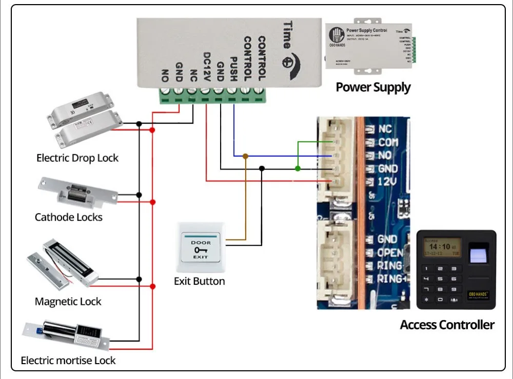
Qel riser diagram. A wiring diagram is a streamlined conventional pictorial depiction of an electrical circuit. Collection of magnetic door lock wiring diagram. Fasten maglock to header plate with the allen head cap screws located at each end of the. Step 4 installing magnet a.
Gallery of External Maglock Wiring Diagram