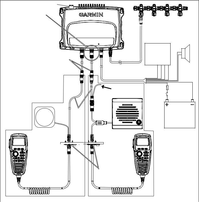
Installing the bulkhead pass through plate 1. Before using the ghc 10 remote you must connect the remote to the magneticcalculates the heading based on magnetic north.

Wy 6970 Garmin Autopilot Wiring Diagram Download Diagram
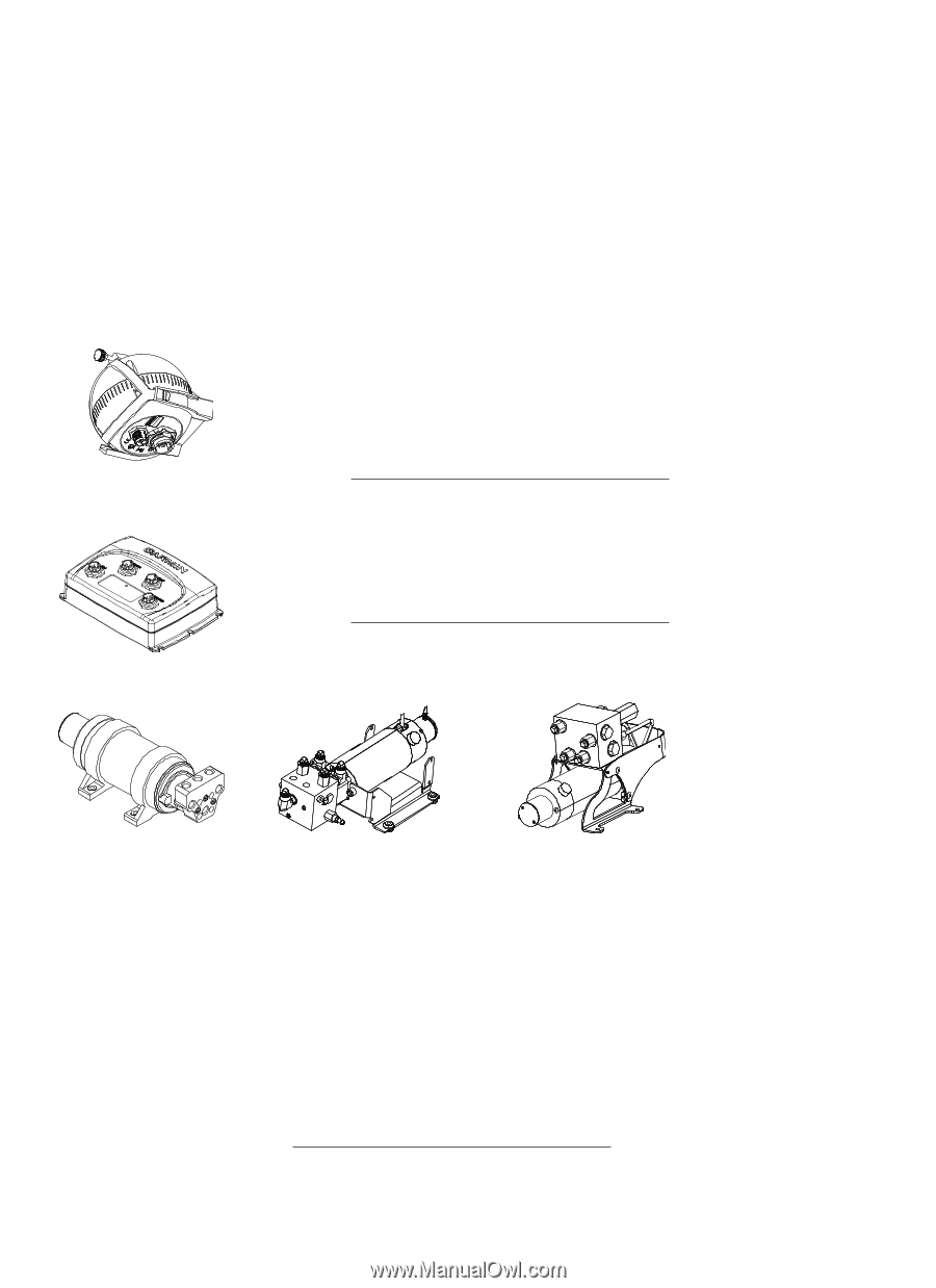
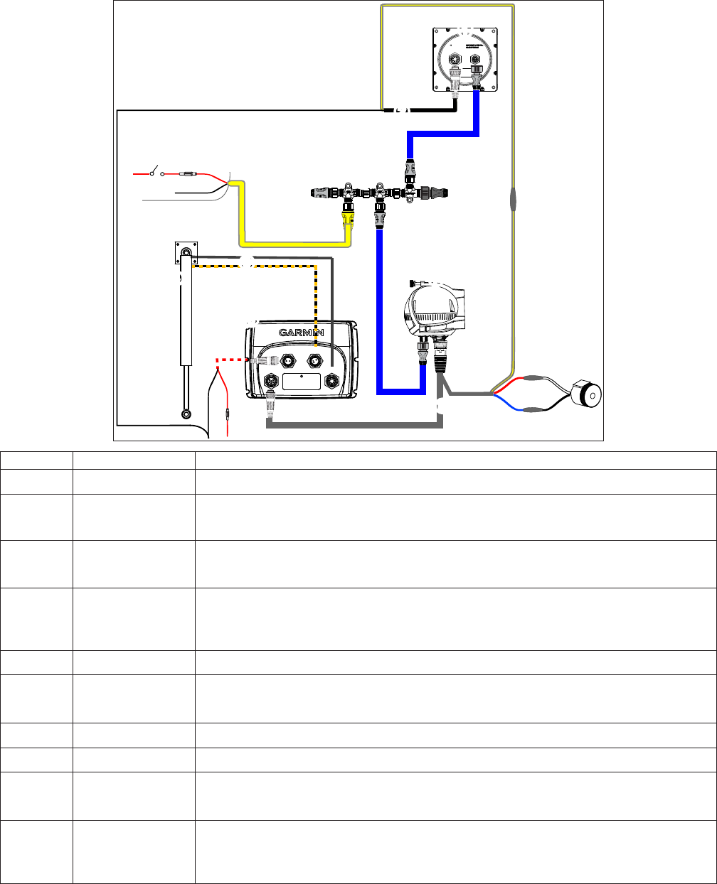
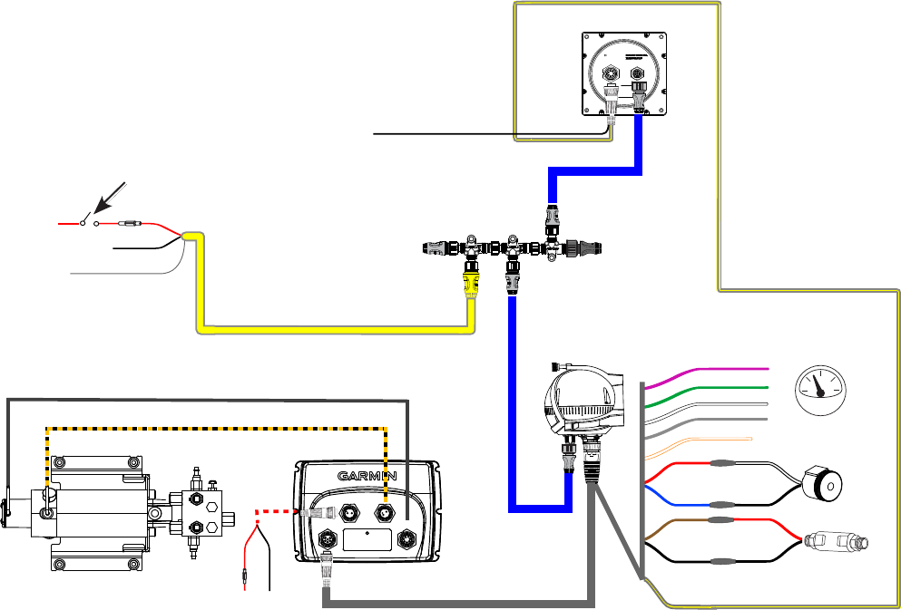
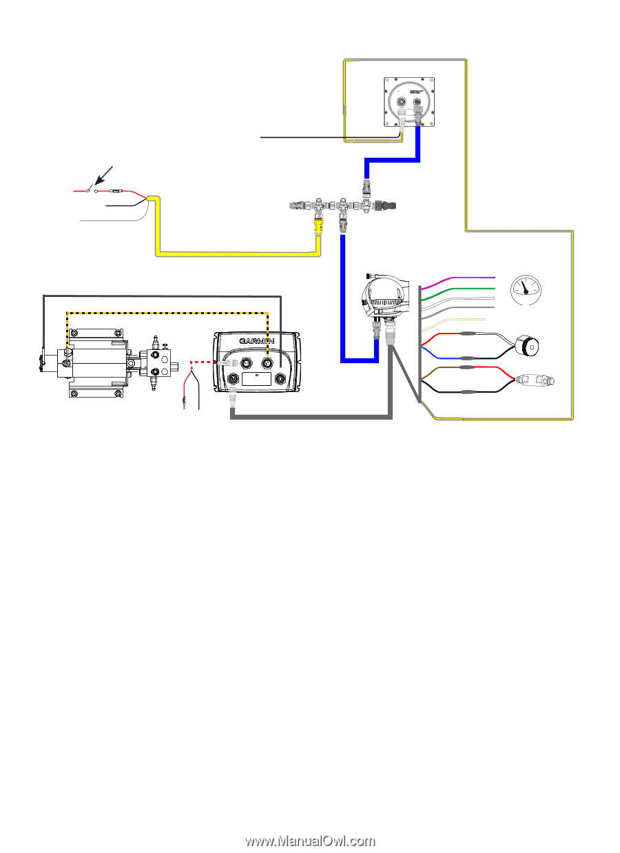
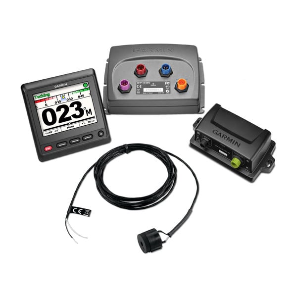
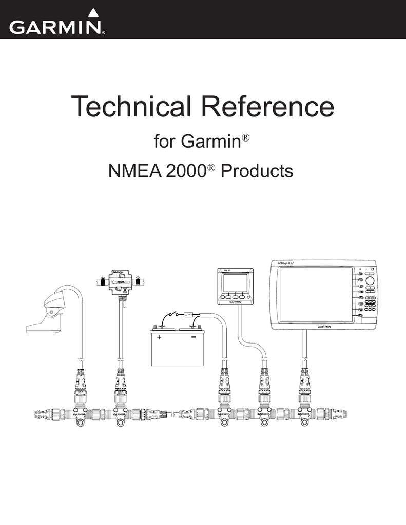
Garmin ghc 10 wiring diagram. Alarm the alarm provides audible alerts from the ghp 10 page 11. The gmi 10 is packaged with the necessary nmea 2000 connectors and cable to either connect the gmi 10 to your existing nmea 2000 network or build a basic nmea 2000 network. View and download garmin ghc 10 quick start manual online. Ghp 10 marine autopilot system ghc 10 ghc 10v. The ghc 10 is the dedicated control unit for the ghp 10 and ghp 12 autopilot systems. Garmin marine autopilot control unit quick start manual.
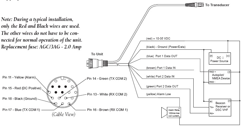
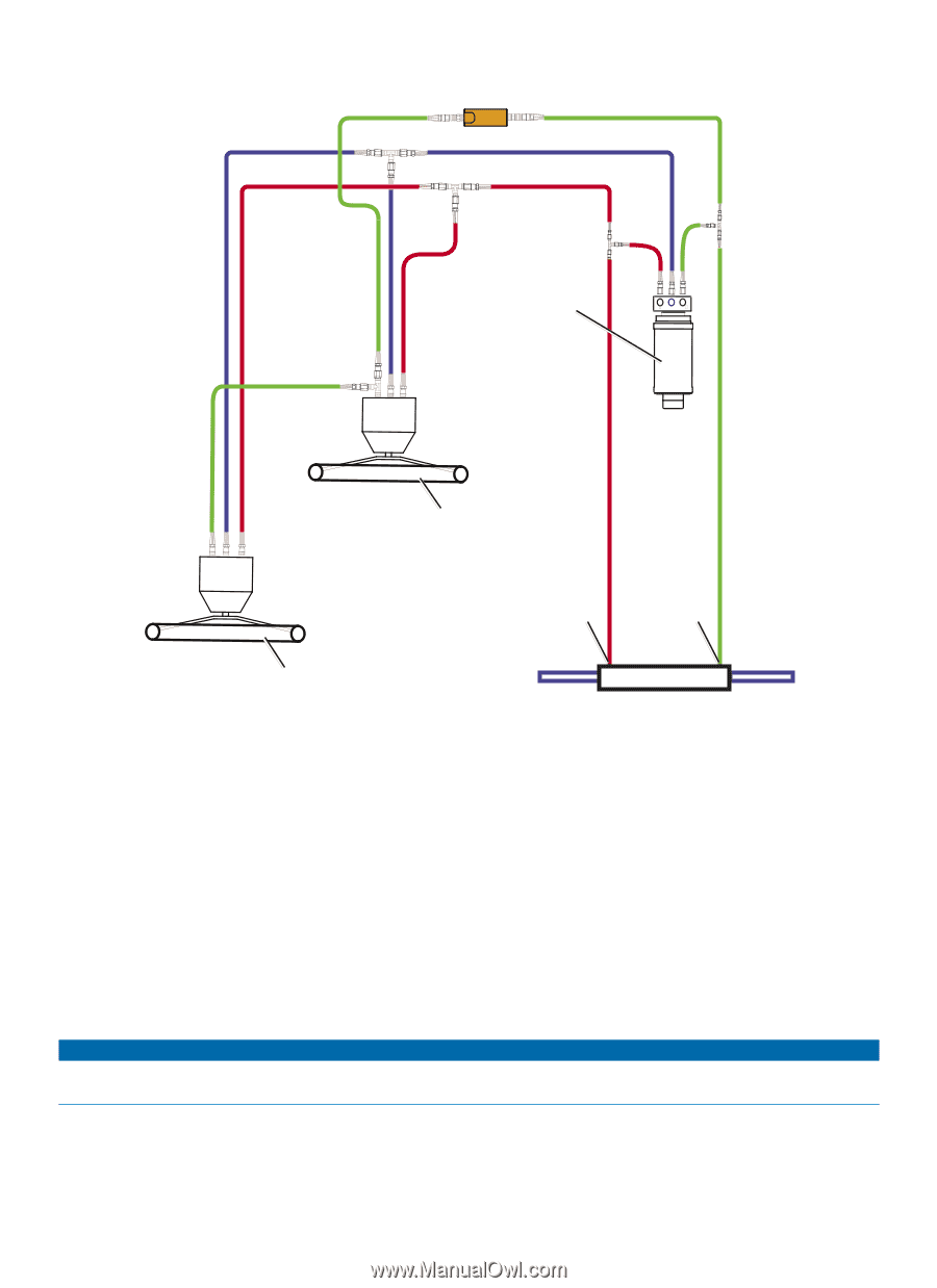
Select or to highlight an option on a menu. The gfs 10 fuel sensor as shown by the shaded components in the box diagram is intended to be connected to an existing nmea 2000 network on. Contact your local garmin dealer or garmin product support for ordering information. Settings connecting the ghc 10 remote headingset the reference used in calculating heading information. This cable is used to connect to an optional nmea 0183 compatible gps device and to the accessory turn on of the ghp 10. Handle your boat with convenience and safety.
010 11057 00 ghc 10 nmea 0183 data cable this cable is included in the ghc 10 box. Follow the directions and reference the diagrams on page 5. T connector is included with a garmin gfs 10 fuel sensor. The ghp 10s simple interface makes operation a cinch. A nmea 2000 power cable terminators an additional dropbackbone cable and additional t connectors are not included with a gfs 10 fuel sensor. Manual conventions in this manual the ghp autopilot system is referred to as the autopilot and the ghc 10 control unit is referred to as the device.
Ghc 20 nmea 0183 data cable this cable connects the ghc 20 to the yellow wire of the ccu and to the same ground as the ecu page 12. If the ghc 10 cable is not long enough to reach the radio location install a cable extension not included between the ghs 10 cable and the radio as shown on the layout diagram. The ghp 10 is controlled using a ghc helm control unit. The simple interactive interface of the ghc 10 gives boaters the confidence and security of controlling the heading of the boat at the press of a key. Ecu power cable this cable powers the ecu page 10. Your ghc 10 must be connected to a nmea 2000 or nmea 0183 compatible chartplotter to use route to.
If more than one ghc 10 device is wired to turn on the autopilot you must turn off all of the wired ghc 10 devices to turn off the autopilot. Install the active speaker wiring harness though the bulkhead. Ghc 10 marine equipment pdf manual download. This control unit communicates with the autopilot system via a nmea 2000 bus so autopilot heading data can be shared easily with other devices.
Gallery of Garmin Ghc 10 Wiring Diagram