When and how to use a wiring diagram. Wiring diagram for exterior lights.
Practical Tips Can Bus Kmp Drivetrain Solutions
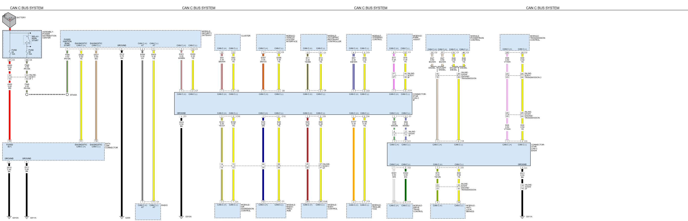
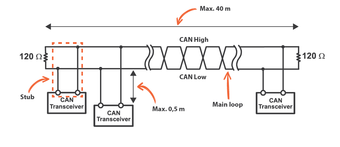
Can wiring diagram. This article covers the basics of can bus wiring to show a simple can bus wiring diagram and how to wire up a can bus cable. The db9 is also known as 9 pin d sub db 9 de 9 serial connector rs232 connector or null modem connector. A wiring diagram is a simple visual representation of the physical connections and physical layout of an electrical system or circuit. Not connected 5 2 7 5 shield at outer wire shield at inner wire shield dsub9 connector female or male pin designation dsub9 connector female or male can wire with. It covers wiring for the common db9 plug and socket often used with can bus test equipment. Lets try this again.
Can wire with connectors canl 120 ohm canh cangnd shield 9 1 4 6 9 3 8 1 6 7 2 3 canl canh cangnd 120 ohm nc. On this page is a how to video some coworkers and i put together. Wiring diagrams can be helpful in many ways including illustrated wire colors showing where different elements of your project go using electrical symbols and showing what wire goes where. On a car the can bus is usually available via the obd port. So you see there are over 17 pages of car wiring diagrams just dealing with engine performance sensors for this one year make model. In fact a typical service manual will contain dozens of these schematics that can help with proper diagnosis and repair.
This is why a good diagram is important for wiring your home accurately and according to electrical codes. Mechanics use car wiring diagrams sometimes referred to as schematics to show them how automotive manufacturers construct circuits. Ask for the wiring diagram for a maf sensor on a 2000 toyota camry without any other information and there is no way anybody can help you. It shows how the electrical wires are interconnected and can also show where fixtures and components may be connected to the system. Keep your diagram nearby.
Gallery of Can Wiring Diagram