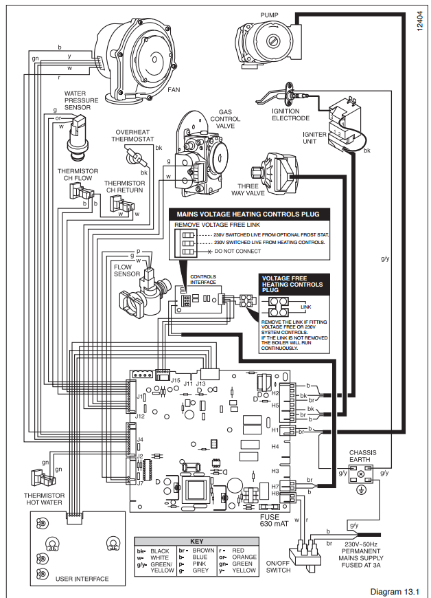
Glow worm boiler wiring diagram ultracom sxi installation service manual boilers glow worm glow worm boiler wiring diagram wiring diagram is a simplified suitable pictorial representation of an electrical circuit. Glow worm bbu 544.

Wrg 8538 Jaguar Wiring Diagram 2000
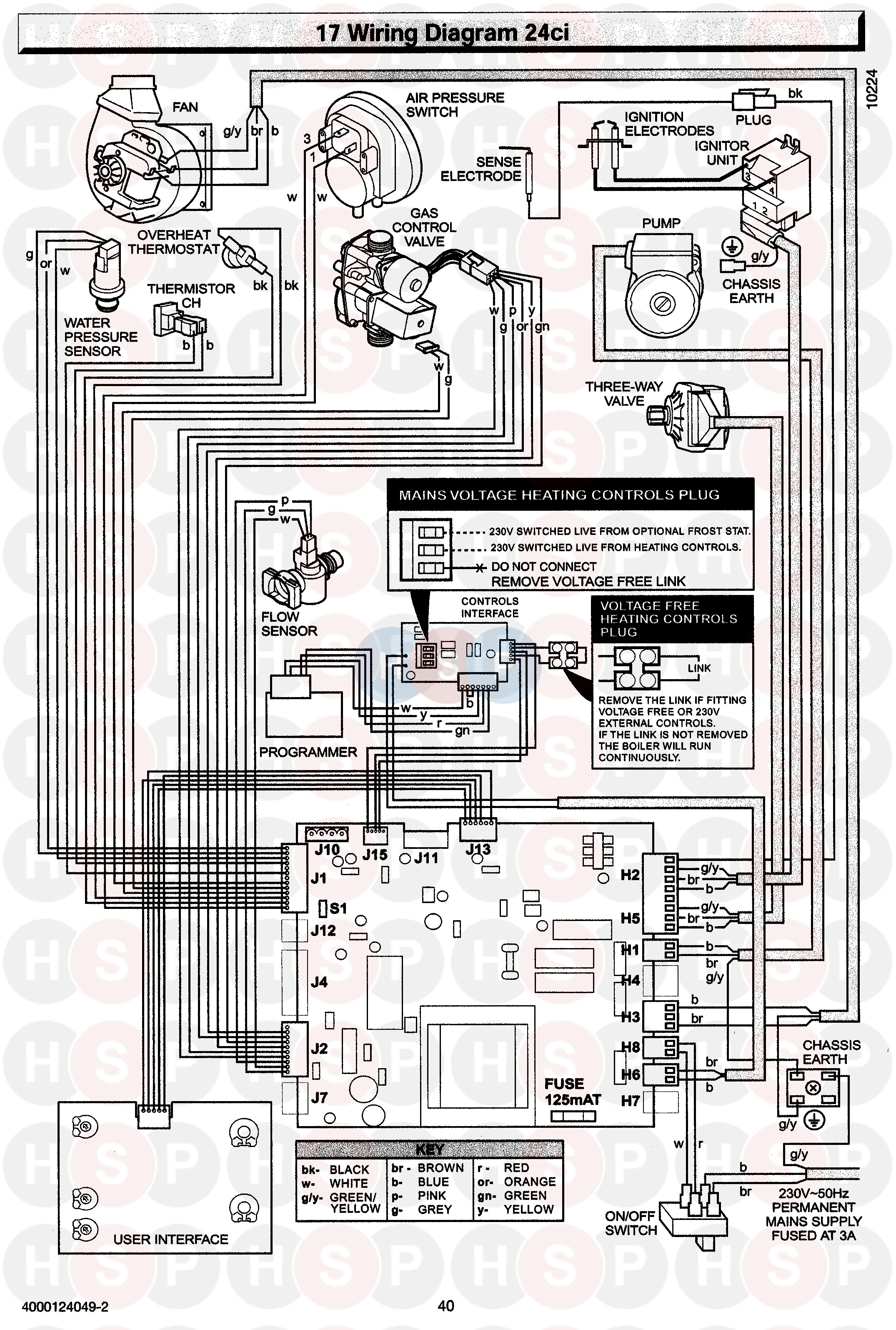
Glow worm wiring diagram. Smart wiring centre₂ is a value solution for those looking for single or two zone heating for simple boiler multizone heating systems with cylinders. It shows the components of the circuit as simplified shapes and the capability and signal contacts amongst the devices. 103 system controls if you are fitting the glow worm options board kit please refer to the instructions supplied with the kit for the system wiring. How to wire a glow worm e bus control. Glow worm bbu 562. 002016717501 0213 glow worm introduction 1 instructions guidance 11 product documentation the instructions are an integral part of the appliance and must be handed to the user on completion of the installation in order to comply with the current regulation.
G wiring diagram 30 kw. Controls wiring for glow worm boilers wiring a glow worm climapro2 rf and climapro1 control duration. Glow worm betacom 24a. Can control up to two heating zones and one domestic hot water zone. Glow worm bbu 452. Positioning of the opening of a fan supported flue gas pipe.
I have a glow worm fuelsaver mk2 and have just purchased a wiring centre to tidy up the mess i currently have. Glow worm energy 18r pdf user manuals. Slacken the cable strain relief and route the pump electrical supply cable and connect as shown in diagrams 101 and 102. Glow worm betacom 2 24. View online or download glow worm energy 18r installation and maintenance instructions manual. This manual provides a step by step process for fault finding in the glow worm combi boilers as well as information on replacing parts and troubleshooting basic issues.
Glow worm bbu 454. Carefully read the manual to understand all the information. Allows glow worms intelligent controls to be used with ultracom and flexicom heat only and system appliances. This is the problem the circuit board asks for live neutral and earth for the boiler which is fine but the boiler also has a yellow lead and ive no idea where that should go. Glow worm 24 ci. Glow worm 23 c.
The trouble shooting manual is linked below with an easy pdf download troubleshooting manual glow worm. Wwwglow wormcouk to be left with the user installation and instructions for use smart wiring centre kit part no. H position of the opening in the airflue pipe. Glow worm betacom 28a. Glow worm betacom 3 24c a h. It is important that the warnings be followed when conducting specific troubleshooting options and that only.
Glow worm 18 si. Glow worm betacom 24c. Glow worm betacom 2 28.
Gallery of Glow Worm Wiring Diagram