Truly we have been noticed that stewart warner gauges wiring diagrams is being one of the most popular subject right now. So that we attempted to find some good stewart warner gauges wiring diagrams picture to suit your needs.

Gm Fuel Gauge Wiring Alpasaw 10 Brillenstudio Weichert De
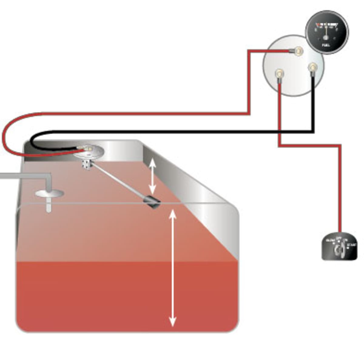
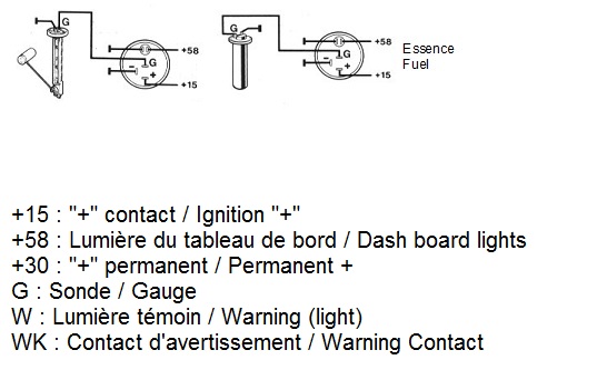
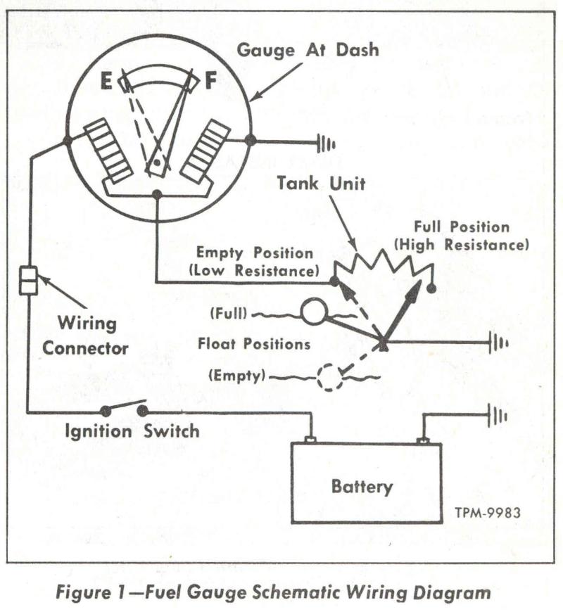
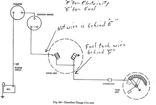
Fuel gauge wiring diagram. Super easy boat wiring and electrical diagrams step by step tutorial duration. A wiring diagram is a simplified standard pictorial depiction of an electrical circuit. It shows the elements of the circuit as streamlined forms as well as the power as well as signal links between the devices. It shows the parts of the circuit as simplified shapes and the power as well as signal links between the devices. It is recommended that insulated wire terminals preferably ring type be used on all. To test senders the resistance values are shown at minimum and full gauge scales.
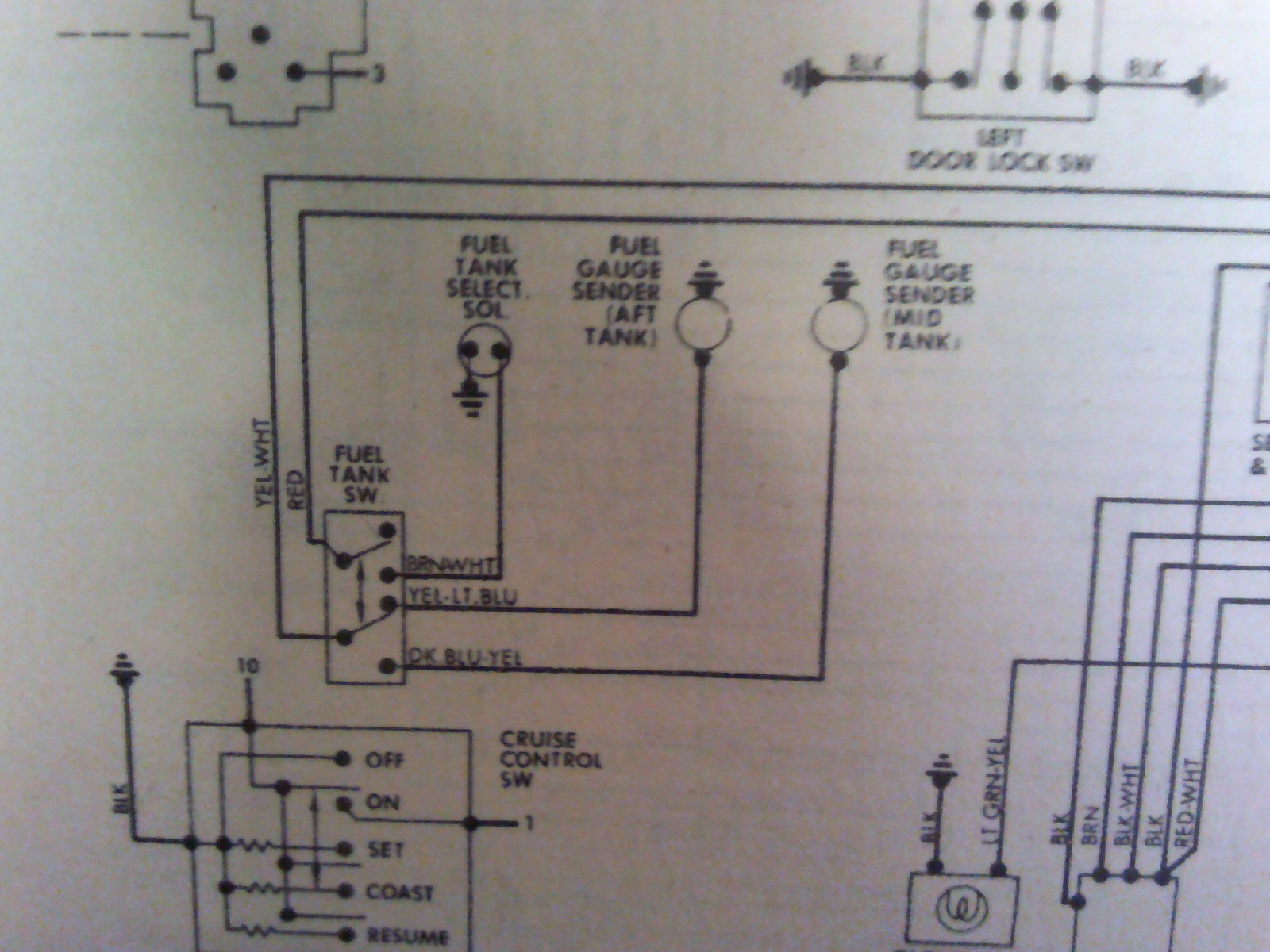
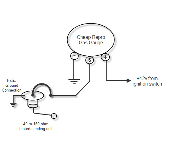
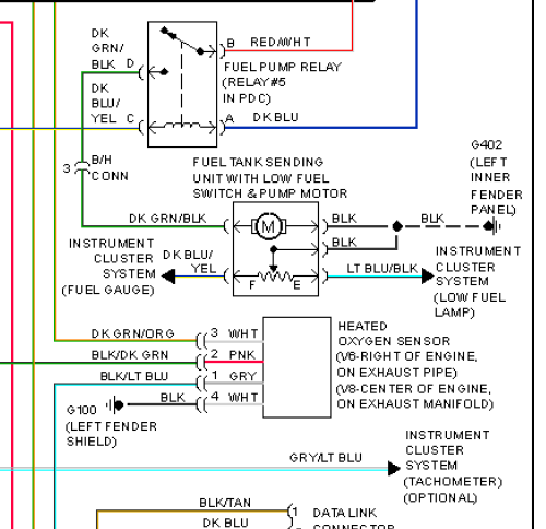
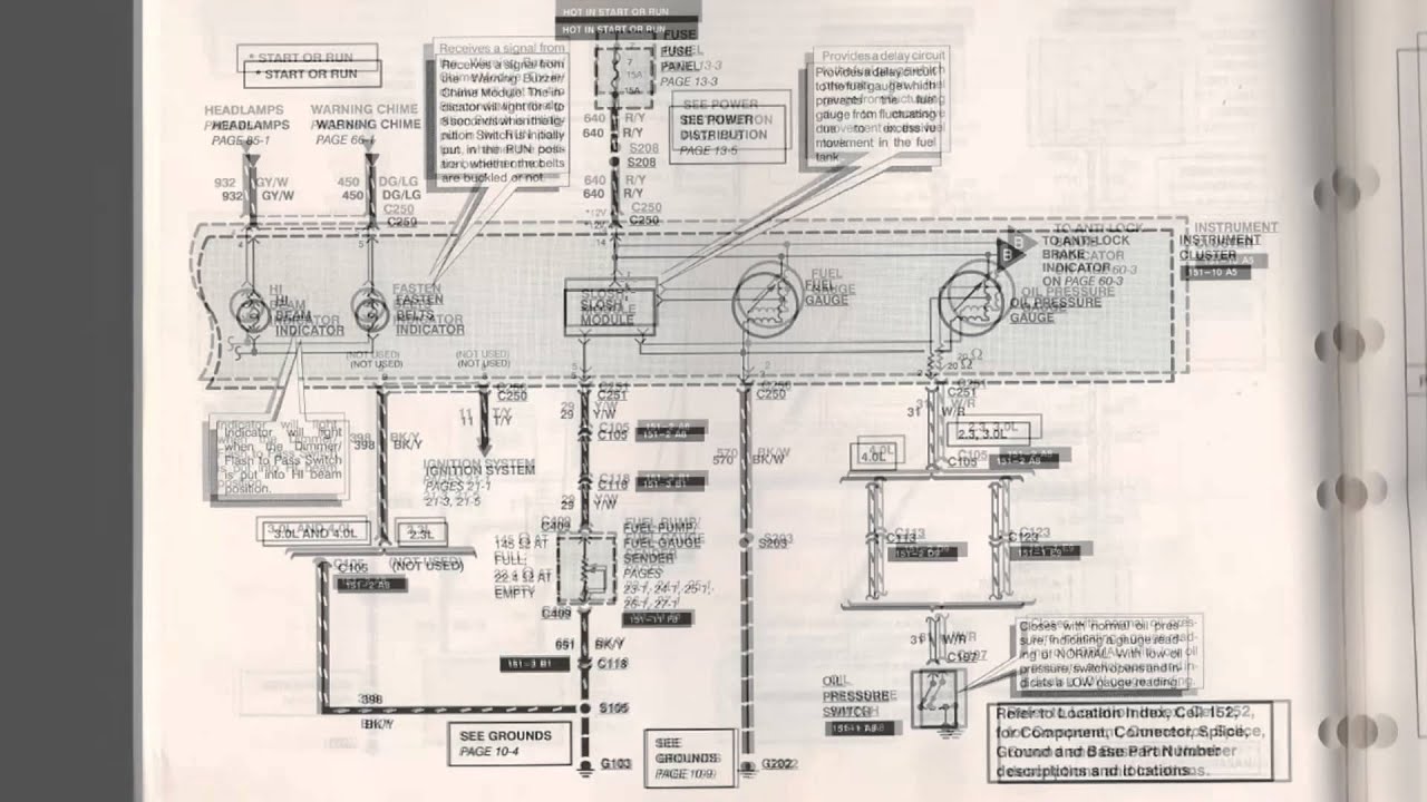
A wiring diagram is a simplified traditional photographic representation of an electrical circuit. See diagram on the next page for connections standard case 3. How to wire fuel gauge and sending unit complete explanation old crows classic cars. Fuel gauge sending unit wiring diagram. Fuel systems marine voltage i to g terminal 10 to 16 volts. Moeller gauge wiring diagram 4 universal electric fuel sender instructions electric fuel.
Assortment of fuel gauge sending unit wiring diagram. Connect a wire to the gauge stud marked s signal and secure with nut and lock washer. Fuel within stewart warner gauges wiring diagrams image size 429 x 298 px and to view image details please click the image. Marine fuel gauge wiring diagram download variety of marine fuel gauge wiring diagram. Connect opposite end to the fuel level senders signal wire or terminal. Gauge pointer should be at the position shown in the lower portion of the diagram.
Gallery of Fuel Gauge Wiring Diagram