The function is the very same. The basic circuit diagram shows which wires go on the switch and which ones are joined together.
Figure 5 Wiring Diagram Model Oeh 34 60 Eng 1
Epo wiring diagram. Obtaining from point a to direct b. A wiring diagram is a simplified conventional photographic representation of an electric circuit. It provides detailed electrical and physical specifications diagrams. A very first look at a circuit representation may be complicated however if you could read a train map you could check out schematics. Chat now with a gasboy sales representative to get your questions answered. Collection of apc epo wiring diagram.
Fill out a form to request a quote from a gasboy sales specialist. Literally a circuit is the course that allows electrical energy to. Attend a product demo. Get a product quote. Next is joining the some of the wires together. The controls on all of these units are powered by a 24 volt transformer.
It shows the way the electrical wires are interconnected and will also show where fixtures and components could be connected to the system. With just two wire terminals on the 24 volt side. There should be a wiring diagram glued to the inside of the units electrical control panel however. Chat now with sales. Apc epo wiring diagram a beginner s overview of circuit diagrams. You can route the red wire attached to the 24 volt side of the transformer through your normally closed epo contacts.
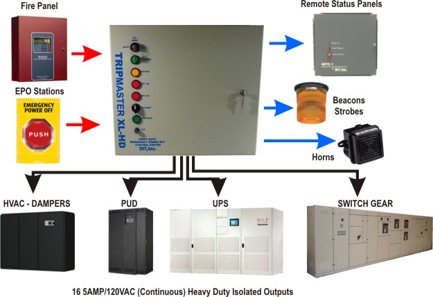
Plus when you bend the wire into a curved shape it retains it better. It shows the parts of the circuit as streamlined shapes and also the power and signal links between the devices. Only certified electricians may install the system and the wiring to the products it the emergency power off epo system consists of one or more wall mounted push button epo boxes. Emergency power off circuits application note an 16 app note an 16 rev. 20 1 1995 and 1999 teal electronics corporation the emergency power off epo button is a common feature in many medical industrial and data processing facilities. A wiring diagram usually gives details concerning the loved one placement and also arrangement of tools and also terminals on the gadgets in order to help in structure or servicing the tool.
A wiring diagram is an easy visual representation in the physical connections and physical layout of an electrical system or circuit. Epo circuits provide a fast simple method of shutting down power to a room or piece of equipment. Specifications electrical inputoutput voltage 24vdc 48vdc240vacexternalcircuit current 1aat24vdc 1aat48vdcexternalcircuit frequency 5060hz circuitsqty 9. In this post i am just tell you about wiring of single epo button with shunt trip mccb breaker. The diagram in cascade multiple epo. March 28 2019 by larry a.
The solder on the wire provided mechanical strength and keeps the wires together when the screw is tightened down. The diagram in cascade multiple epo. In industrial state electric operator duty is to operate the machinery and his duty is on the front of main panel board. Fe 361 atlas master satellite field wiring diagram. Shunt trip breaker wiring diagram with epo button.
Gallery of Epo Wiring Diagram