The entire cycle is then repeated but with load 2 energized first. I bought a dpdt cross wired unit but only have one control switch.
Air Compressor Alternating Relay Wiring Diagram Alternating
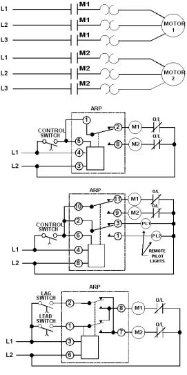
Alternating relay wiring diagram. Make sure the wires are connected to the correct terminal number on the socket. The switch when moved in either direction applies both power and ground directly to motor legs without the use of any relays. The model 261 series alternating relays are extremely versatile and can be used in many other configurations besides those shown. Except at the switch in this case both motor legs rest at ground. The alternating relay toggles to the load 2 position. The top of the socket.
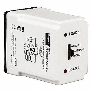
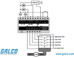
Door locks 5 wire alternating 12 volts positive type c relay wiring diagram. The red led marked load 1 is on. Any type of switch float pressure etc can be used as the control switch. The wiring diagram on the relay is the view looking towards the bottom of the relay vs. Any type of switch float pressure etc can be used as the control switch. In the off state figure d both the lead switch and the lag switch are open the alternating relay is in the load 1 position and both load 1 load 2 are off.
Connect wiring to the socket as indicated in the following examples. However it must be connected as shown from l1 to the. Connect wiring to the socket as indicated in the following examples. However it must be connected as shown from l1 to the. 11 3 the model 261 series alternating relays are extremely versatile and can be used in many other configurations besides those shown.
Gallery of Alternating Relay Wiring Diagram