February 8 2019 by larry a. A wiring diagram is a streamlined traditional pictorial representation of an electric circuit.
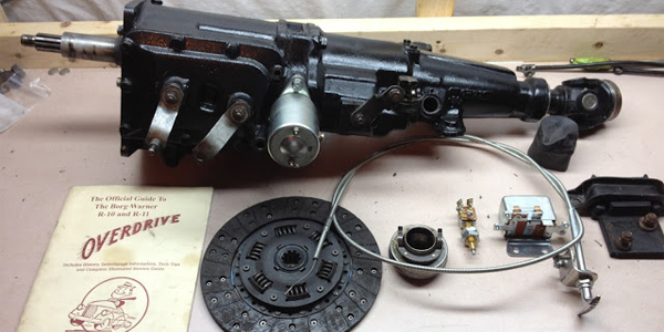
Parts Borg Warner Overdrive Parts Fifth Avenue Internet Garage
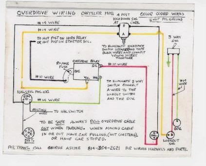
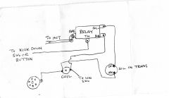
Borg warner overdrive wiring diagram. The wiring harness can be fabricated by connecting the terminals and components as shown in the wiring diagram see image while it seems. Overdrive was last used in ford passenger cars in 1967. A few notes reverse lockout switches were discontinued by the factory somewhere around the early 1950s. Wellborn collection of borg warner overdrive wiring diagram. They are not needed and your overdrive will work fine without one. A wiring diagram is a streamlined traditional photographic representation of an electric circuit.
A wiring diagram is a streamlined standard photographic depiction of an electrical circuit. The dpdt relay in my circuit substitutes for the special kickdown switch that mounts above the gas pedal in the old vehicles. It shows the parts of the circuit as simplified forms as well as the power as well as signal connections in between the devices. As you can see it is pretty simple and basic. Assortment of borg warner overdrive wiring diagram. Collection of borg warner overdrive wiring diagram.
Most original ones no longer work so just bypass the switch. This diagram can be used for most any borg warner overdrive application. If you have an all original truck with the overdrive this diagram should be usable. It reveals the parts of the circuit as simplified shapes as well as the power as well as signal connections in between the gadgets. It reveals the parts of the circuit as simplified forms and the power as well as signal connections between the gadgets. The picture above shows the borg warner overdrive wiring diagram.
This is borg warners original wiring diagram scanned from a 1965 chiltons manual. The borg warner overdrive transmission began its life in the 1930s and was last used anywhere in the automotive industry in ford trucks in 1972.
Gallery of Borg Warner Overdrive Wiring Diagram