See nfpa 70 article 760. Wiring diagrams for siemens nema contactors and starters.

Gamewell Fci S3
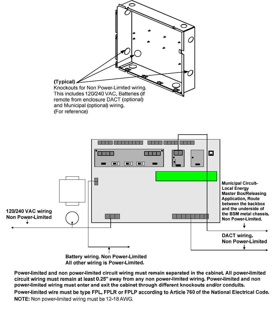
Dact e3 wiring diagram. It can also be used to migrate and create standardized diagrams from legacy systems. E3 series broadband installationoperation manual pn 9000 0577l4 2022016 3 installation precautions adherence to the following will aid in problem free installation with long term reliability. Wiring resistance must not be more than that shown on the field wiring diagrams. To reduce errors and help in servicing the system all conductors should be tagged or otherwise coded and logged at installation to identify circuit assignment and polarity. Digital alarm communicator transmitter that is programmable via the control panel wiring diagram main termination board technical data environmental operating temperature. Disconnect all sources of power before servicing.
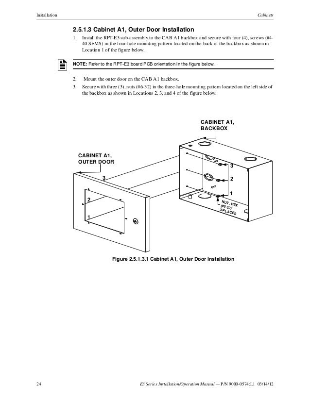
E3wiring diagram generator functionality is integrated in the e3cable user interface with its own easy to use toolbar. The diagrams created by e3wiring diagram generator can subsequently be modified using e3cable. For instructions on how to install the dact e3 refer to the following documents. If the conductors are. E3 series. F c siemens industry inc.
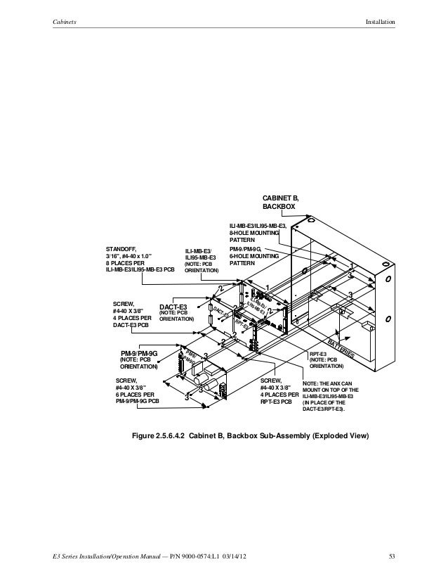
A broad range of diagrams from simple from to connections to more complex environments can be processed. Either unit can be easily connected to the backbo x or sub assembly plate depending on the cabinet module. E3wiring diagram generator e3wiring diagram generator automatically generates schematicswiring diagrams for development service and after sales. For example variants splices inline connectors and wiring display symbols are all supported. Warning several different sources of power can be connected to the fire alarm control panel. Typically the dact e3 module mounts on standoffs on top of the left side of the ili mb e3ili95 mb e3 or slp smart loop panel module.
Gallery of Dact E3 Wiring Diagram