Note regarding audio amplifier in figures 3 4 above. See notifier installation manual for detailed information.

Product Catalogue Catalogue Fire And Gas Detection Systems
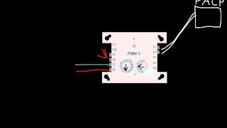
Notifier m701 wiring diagram. Notifier nfse manual online. Connecting a releasing device to the fcm 1 rel. It must be mounted in a suitable cabinet meeting the applicable safety standards. 16112018 16112018 3 comments on notifier fcm 1 wiring diagram. The m701 control module provides a monitored single output circuit for use with polarised loads sounder circuit which requires a suitable power source 7vdc 30vdc for the connected load. Notifier nfs manual online.
M701 240 din mounts onto standard 35mm x 75mm top hat din rail. Connect modules to listed compatible notifier control panels only. Wiring to the m701 240 din is via plug in type terminals capable of supporting conductors up to 25mm². Connecting a releasing device to a fcm 1 module connecting an nbglra agent release abort station. M710 wiring see figure 3 for wiring details. Each led can be set by panel command to pulse green each time the module channel is polled.
If using the vds optional polarised resistor eol device part no. 1 audio circuit wiring must be twisted pair as a minimum. Module does not supervise controlled circuits. M200e eol rd note that the eol device red wire connects to terminal 8 and the grey wire to terminal 9 as monitoring voltages are reversed. M720 dual channel input module the m720 is a dual channel module used for the monitoring of normally open contact fire alarm and supervisory devices. M701 wiring the m701 can be wired for either supervised or non supervised operation see figures 5 and 6 overleaf respectively.
The m700 series modules are designed for use with any notifier protocol fire alarm control panel and include selectable loop isolation in every device. See figure 2 for connections. Releasing applications c limited energy cable cannot be used to wire a. It has two tri colour leds one referring to each channel.
Gallery of Notifier M701 Wiring Diagram


-500x500.jpg)