Electrical connection 15 81 connection with auma plug socket connector s sh se 17 9. Electronic device id 108 132.

Fn 4855 Addition Limitorque Valve Actuators Diagram
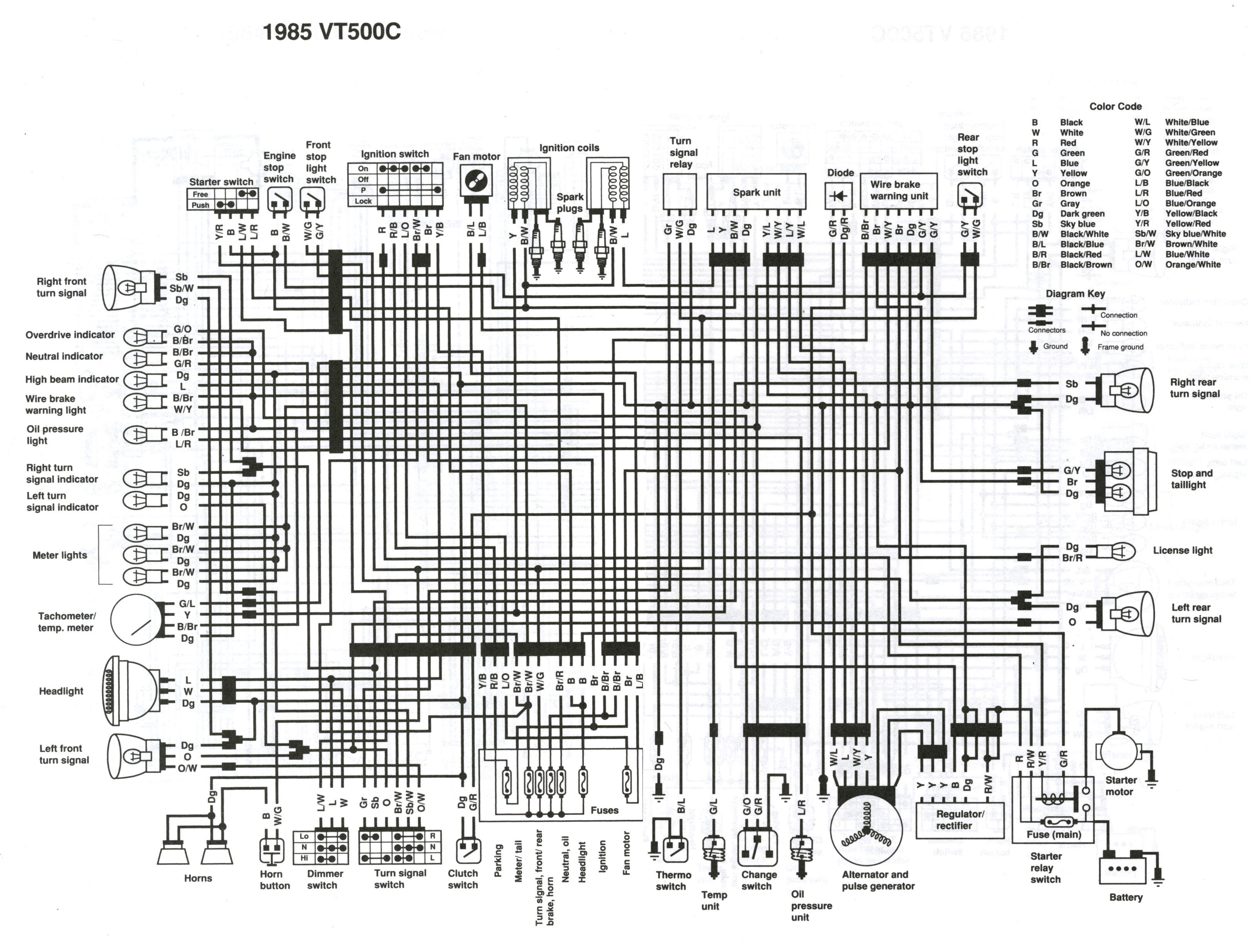
Auma mov wiring diagram. Diagnostic bluetooth connection 108 133. Here you will find the suitable software for your auma actuators. If the pop up blocker is turned on in your browser you are not able to view the wiring diagram. The software provided for download is subject to continual improvement and will be updated without delay with bug fixes if applicable. The wiring diagram opens in a pop up window. Wiring diagram number quotation number.
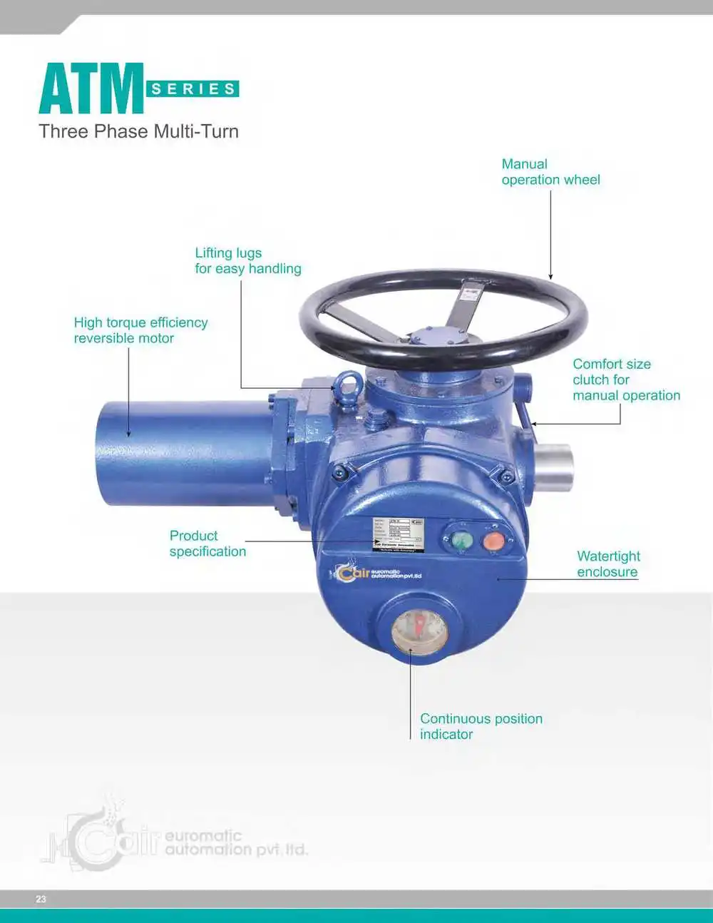
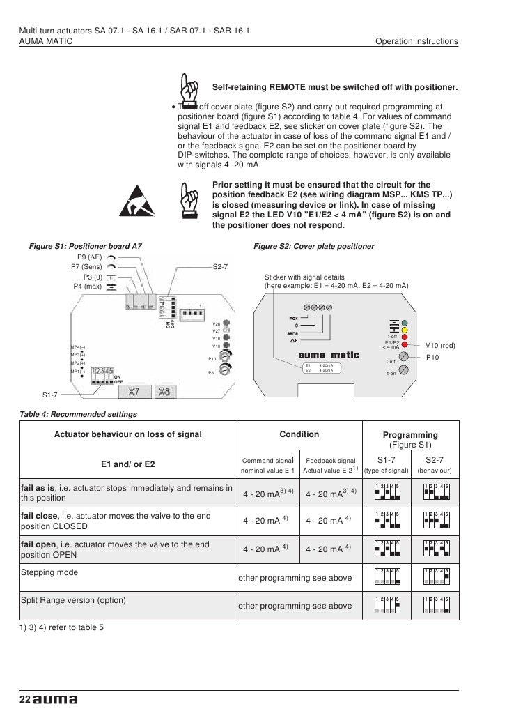
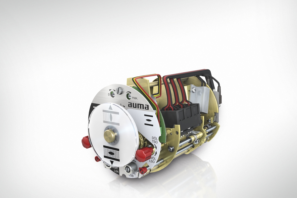
Mounting to valve gearbox 12 7. Transport storage and packaging 10 51 transport 10 52 storage 10 53 packaging 11 6. Selected wiring diagrams under documents attention. Manual operation 19 10. M motor 3 phase ac s 1 dsr torque switch closing clockwise s 2 doel torque switch opening counterclockwise s 3 wsr limit switch closing clockwise. The wiring diagram shows the non rotating multi turn actuator in intermediate position.
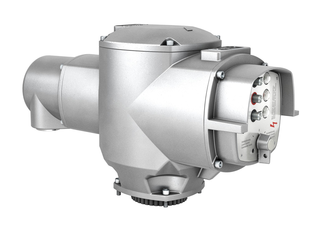
Wiring diagram for standard version multi turn actuator closes valve clockwise. Mounting positions of the local controls 14 8. Diagnostic position transmitter potentiometer 110 135. Service software auma cdt bluetooth 106 13. Additional information to the wiring diagram legend 9 5. Please enter the address of our website in the address of web site to allow box.
Diagnostic interface 109 134.
Gallery of Auma Mov Wiring Diagram