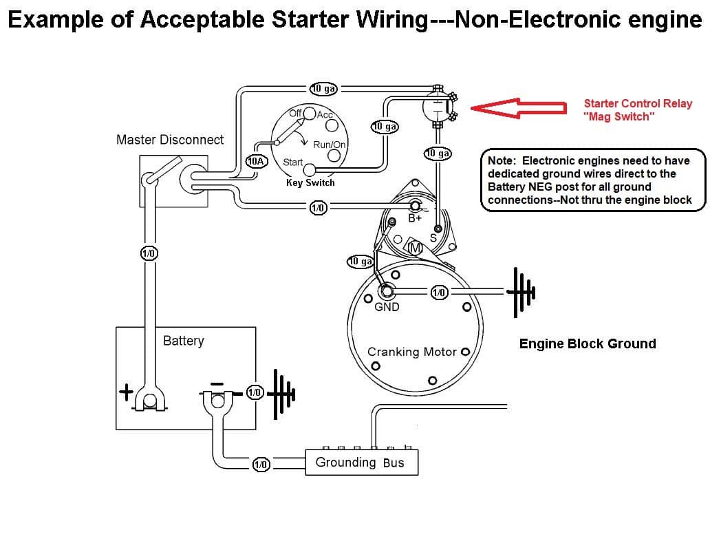
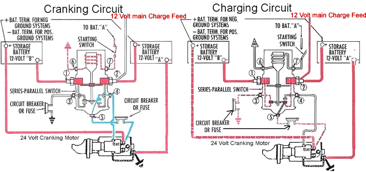
The ac delco 3 wire alternator was used in most general motors products and many types of heavy equipment for a long time which makes it readily available. Grounding insulated starting motors figures 1 2 page 2 this may be an insulated starter replacing a grounded type starter.

Delco Starter Wiring Diagram Delco Remy Alternator Wiring
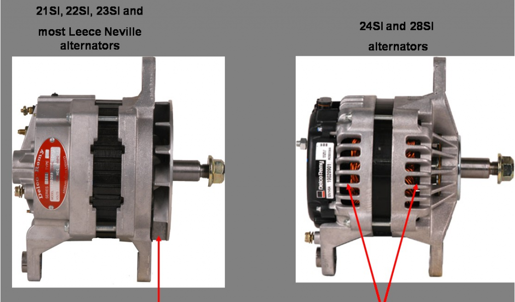
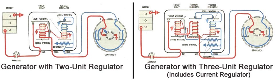
Delco remy wiring diagram. 3 wire ims connected to start switch and 2 wire ims connected to ecm. Retrofitting old stlye delco remy regulator to new style delco remy 50vr regulator. Wiring diagram for garden tractors with a delco remy starter generator here is an example wiring diagram for a garden tractor that is equipped with a delco remy starter generator. The new starter must have the same number of ims leads as the old starter. Rotor with pressed on bearing assembly replacement instructions for 24si. This alternator has the advantages of high output compact design and ease of use.
The common components in a wiring diagram are ground power supply cable and also connection outcome tools switches resistors logic entrance lights and so on. Between those years you may have the cs 130 or the cs 130d alternator. Rotor replacement for 27si. The failure to carefully follow these instructions set forth herein. The wiring hookup is the same for the cs 130 and cs 130d alternators. 1995 1998 was a transitional period for the cs 130.
The 2 wire and 3 wire units are not interchangeable. The gm delco remy cs130 alternator was used on gm vehicles from about 1986 1996. With the proper brackets this alternator can be adapted to any vehicle or. Download how to instructions for replacement parts on delco remy starters alternators. To review a wiring diagram first you have to recognize exactly what essential aspects are included in a wiring diagram and which pictorial icons are made use of to represent them. Replacing delco remy 10si 11si 12si or bosch k1 alternators with 11si alternator.
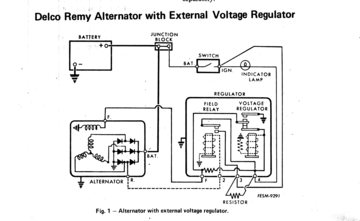
The below diagram also shows our 5 prong 3 position ignition switch and our 4 prong mechanical voltage regulator. With key on power is then transferred through the no charge indicator light to the 1 spade on the alternator regulator connection. This diagram shows the simple wiring diagram for negative ground delco si series alternators the ignition switch is most commonly powered from the starter battery stud but source may vary depending on application.
Gallery of Delco Remy Wiring Diagram