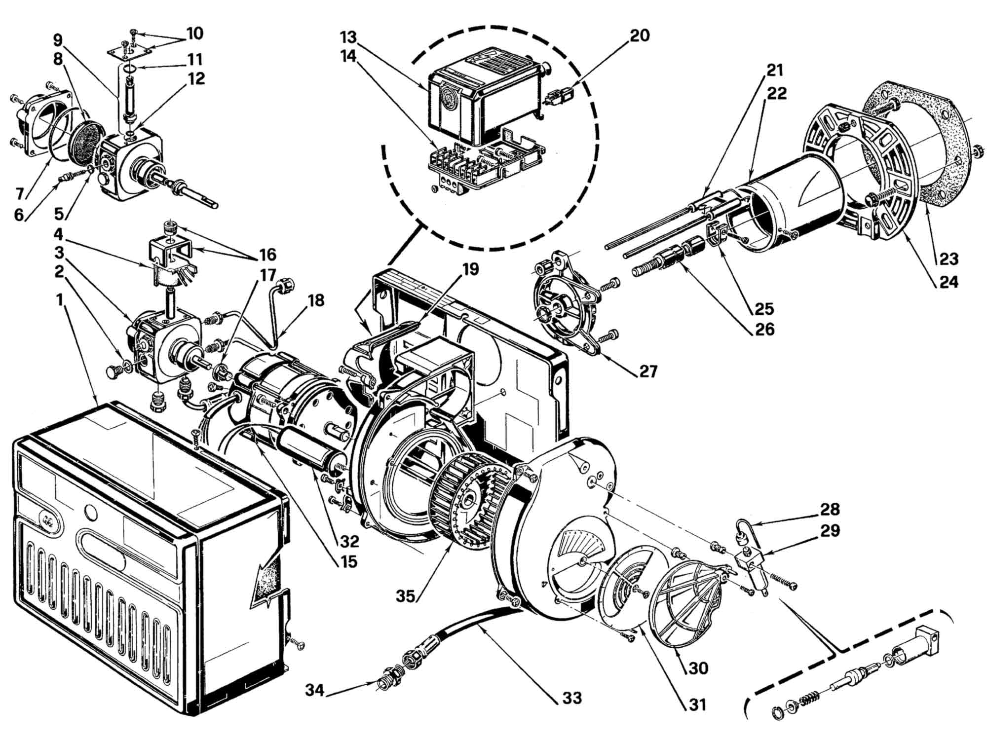
Steven lavimoniere 32744 views. Motor riello part n o.
Roaring Oil Burner Noise Check Immediately For Chimney Fire
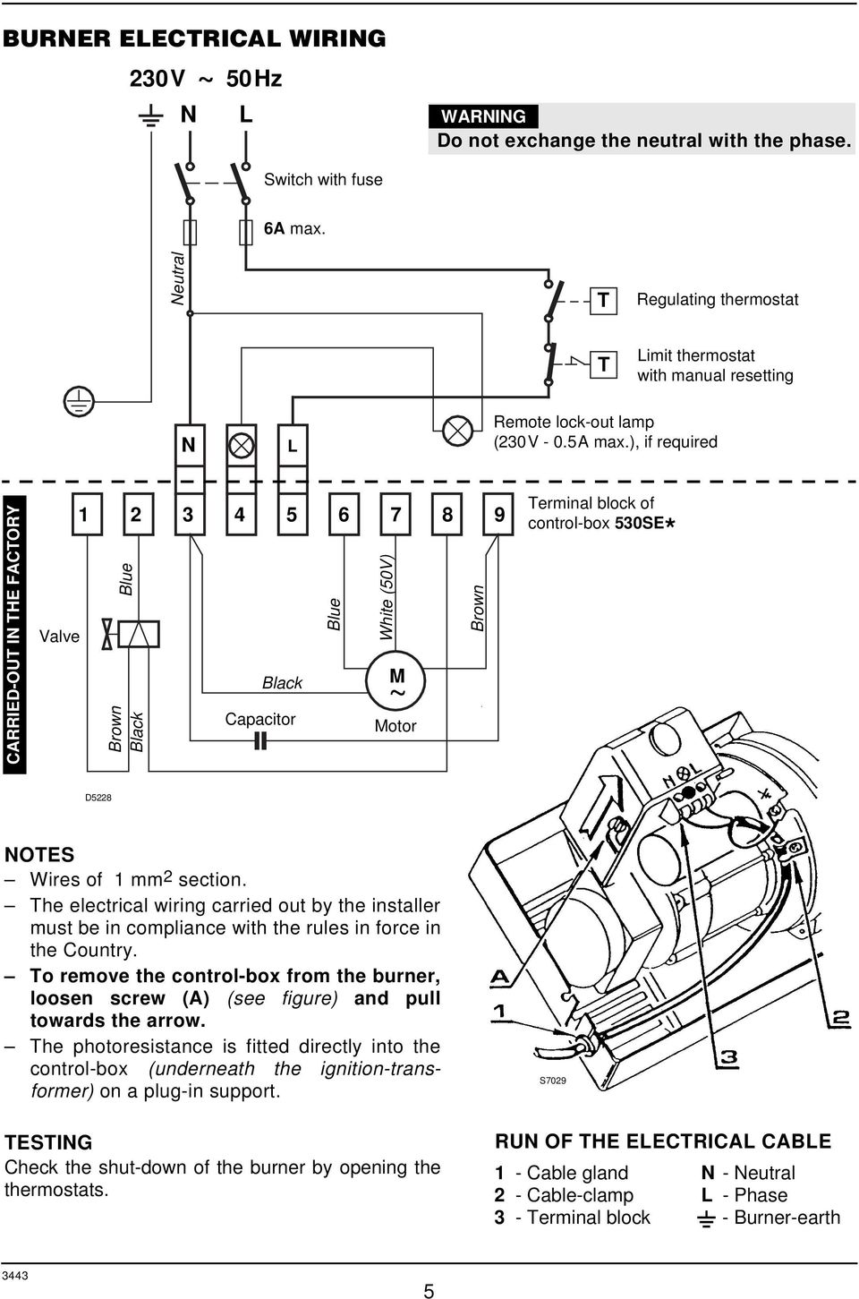
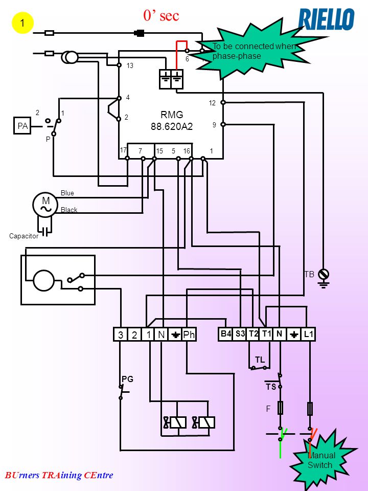
Riello burner motor wiring diagram. 3 t 4 operating limit device. Riello rdb series oil burners red 05s on red 05s off lockout for false flame signal red 02son red off lockout for max n of recycles red 25s on orange 05s on lockout fan motor failure red steady on lockout for no flame after safety. 2800 rpm run current 08 amp motor rated capacitor 125 microfarads pump pressure 130 to 200 psig primary control riello 530 sec riello 530 sec 24v ignition transformer 8kv 16ma burner and mounting flange dimensions model inches 8 1532. Electronic air shutter requires a constant 120v power supply to the aux terminal failure to provide this will result 1n no burner operation or air shutter will not close. This should be 50v ac 3 volts. Motor rl70rs70 riello part n o.
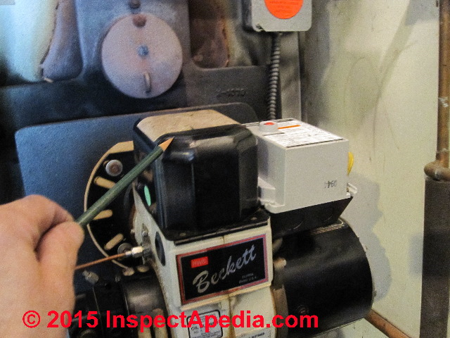
All wiring must be done in. C6501010 standard f3 5 manual rev. This is how to replace a riello burner motor on an oil fired furnace in 10 minuites. Bf5 riello burner with issuestigerloop installednoisey motor duration. The burner may be controlled using either a direct line voltage control circuit 120v ac 60 cycle or a low voltage control 24v ac 60 cycle using models riello or honeywell r8038a 24v relays. If this burner is being installed on a packaged unit burner comes with the boiler or furnace then follow the settings on the oem page as settings may differburner is set for a single line system.
If no voltage present change burner motor. The settings in this manual are for retrofit applications. Which burners are available for single phase electrical supply. Riello 40 series residential oil burners note. As a last resort change the control box 530se. Motor gives 5ovac across.
Motor riello part n o. Application field wiring wiring diagram shown below for standard riello 530 sec primary control box installation note. Boiler diagrams spare parts and user manuals for riello riello motors riello motors 24 hour delivery on genuine manufacturer boiler spares 30 day money back guarantee. Electronic air shutter requires a constant 120v power supply to the aux terminal failure to provide this will result in no burner operation or air shutter will not close. Check voltage on white wire to terminal 7 of 530 se control box. How to test a riello burner electrily with a good multi meter.
Following the wiring diagram on the next page make electrical connections to burner. Motor riello part n o. Application field wiring wiring diagram shown below for standard riello 530 sec primary control installation note.
Gallery of Riello Burner Motor Wiring Diagram