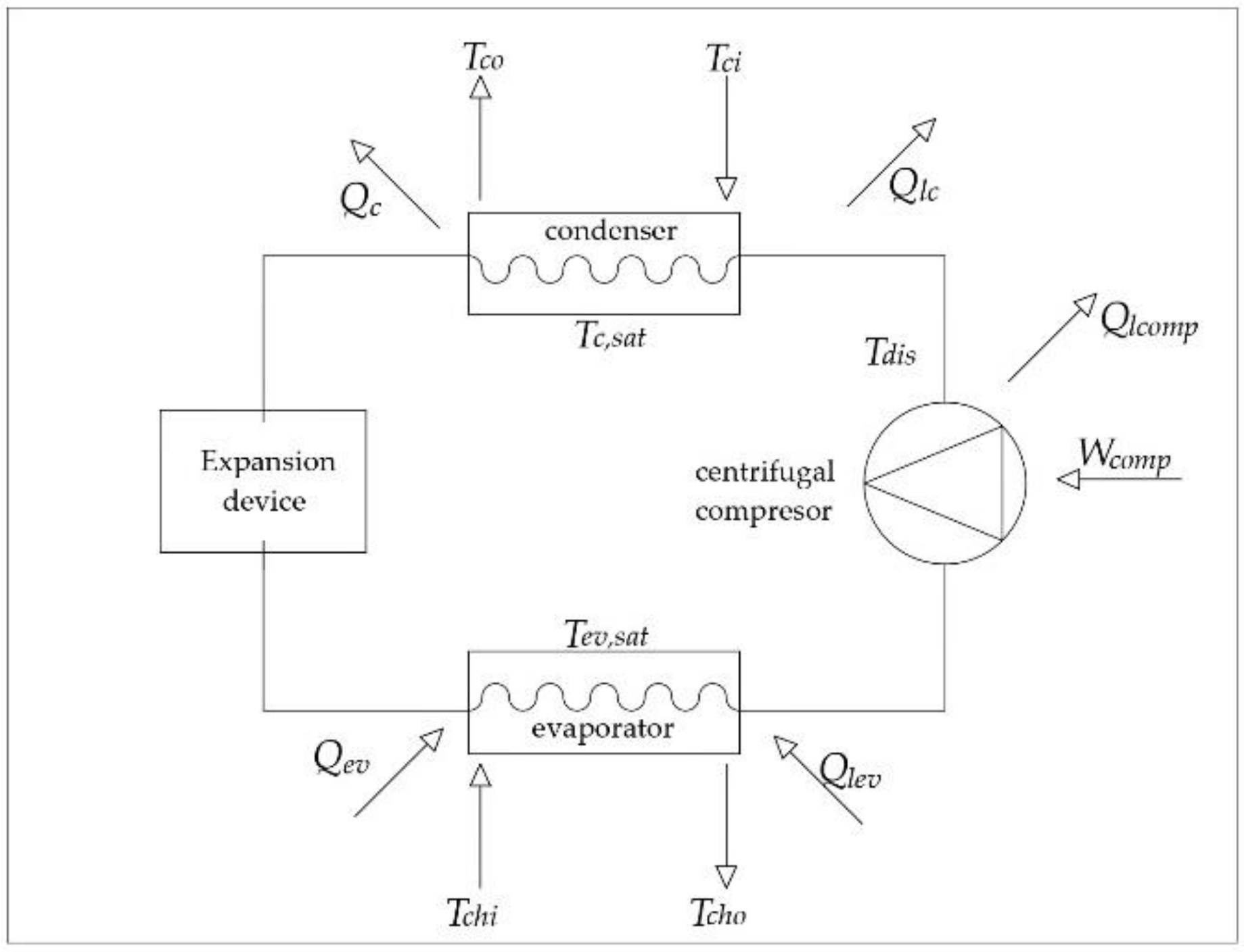
The chiller consists of an. The york model yk millennium chiller is commonly applied to large air conditioning systems but may be used on other applications.
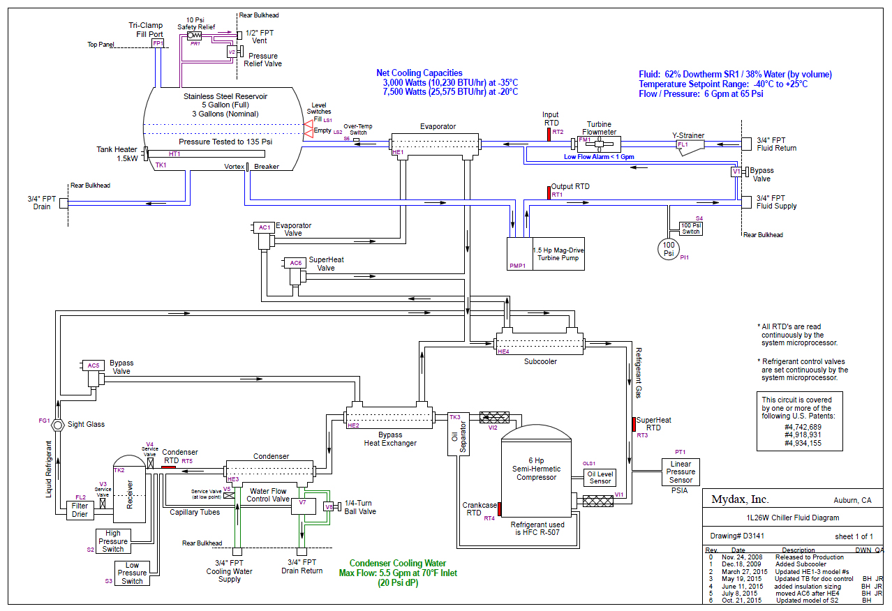
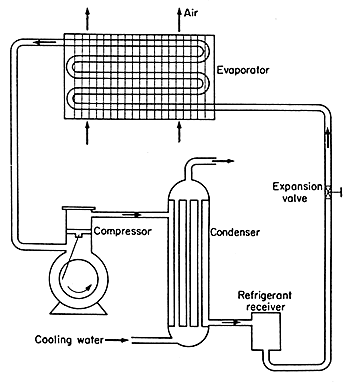
Air Cooled Air Cooled Chiller Diagram
York yk chiller wiring diagram. Wiring diagram yk chiller style g optiview control center w ltc io board with unit mounted low or medium voltage sss unit mounted low voltage vsd with modbus or remote medium voltage vsd 16075 pw8 renewal parts unit 16075 rp1 renewal parts optiview control center 16054 rp1. York international 11 ld10915 display interface board fig. The york model yk maxetm chiller is commonly applied to large air conditioning systems but may be used on other applications. 1 model yk maxe chiller york international. This wiring diagram describes the standard elec tron ic con trol scheme for use with a york vsd. Wiring diagram yk chiller style g optiview control center with remote low or medium voltage ems 16075 pw5 wiring diagram yk chiller style g optiview control center with unit mounted low or medium.
Wiring diagrams optiview control center and sss lv vsd mv vsd with the ltc io board 16075 pw8 wiring diagrams field control modifications 16075 pw4. The york model yk chiller is commonly applied to large air conditioning systems but may be used on other applications. Wiring diagram yk style g chillers field control modifications 16075 pw4 wiring diagram yk style g chillers optiview control center with sss lvvsd with modbus and mvvsd 16075 pw6 wiring diagram yk style g chiller optiview control center with ltc io board with unit mounted. All servicing of product should be performed by a licensed contractor according to local and national code requirements. With seismic certification osp 0045 10 this water cooled chiller can maintain operation in the event of an earthquake making it ideal for sensitive applications like hospitals or data centers. This manual describes the installation of a york yk mod g centrifugal chiller.
Field wiring to be in accordance with the national. 5 display interface board notes. Water nozzles can be located on either end of unit. 16054 pw1 wiring diagram unit with mod a solid state starter. This unit can be shipped as a single factory assembled piped wired package. The york yk centrifugal chiller is built to last.
Nortek global hvacreznor does not endorse any field changes to factory wiring schemes. For details of standard modi fi cations refer to product form 16054 pw7. Wiring diagram œ unit with electro mechanical starter 16052 pw1. 1 model yk maxe chiller form 16073 n1 904 compressor motor optiview control center condenser evaporator 00611vip fig. Add 12 13 mm to nozzle length for fl anges connections. Wiring diagram unit with electro mechanical starter.
Also note that certain field modifications may occur to accommodate the use of other control systems. The chiller consists of an open motor mounted to a compressor with integral.

