Diy pir infrared motion sensor switch smart security led light motion sensor wiring diagram wiring diagram consists of numerous in depth illustrations that display the relationship of varied things. Observe the electrical wires on the motion sensor.

Home Motion Sensor Wiring Diagram
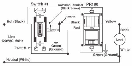
Motion sensor wiring diagram. A wiring diagram is a simplified conventional pictorial depiction of an electrical circuit. The passive infrared sensor consists of three pins as shown below. Never work on energized wires. Refer to your particular model for any specific instructions or connections as various models may have different wiring methods. Typically three wires are attached to a motion sensor. Pir motion sensor light wiring diagram new wiring diagram for a pir motion sensor light wiring diagram wiring diagram consists of many detailed illustrations that display the relationship of varied items.
Go through the given diagram of the pir sensor to understand its pin outs and arrangement in the circuit. Wiring a motion detector head to an existing light fixture. Each component should be placed and linked to other parts in specific manner. It shows the parts of the circuit as simplified shapes and also the power as well as signal links in between the devices. If not the structure will not function as it ought to be. Collection of 3 way motion sensor switch wiring diagram.
It consists of guidelines and diagrams for various kinds of wiring techniques along with other items like lights home windows etc. A motion sensor light switch will automatically detect when someone enters the room and turn on the lights. Pinout of pir sensor. No wiring is necessary to control existing lights. A motion sensor light switch is a great way of saving energy and helping out the planet by making your home greener and more energy efficient. Wireless motion sensor lights a wireless sensor works like the remote control for a garage door opener.
It includes guidelines and diagrams for various varieties of wiring techniques and other items like lights home windows and so forth. Then after a few minutes where no movement has been detected the lights will then automatically shut themselves off. Wiring a motion sensor light diagram motion sensor light wiring diagram australia wiring a motion sensor light diagram wiring a motion sensor light diagram uk every electrical arrangement is composed of various diverse pieces. It reveals the elements of the circuit as streamlined shapes and also the power and also signal connections between the tools. A wiring diagram is a simplified conventional photographic depiction of an electrical circuit. Just screw the receiver into a light socket and mount the sensor anywhere you like.
It sends a radio signal to a receiver that switches on a light. Variety of motion sensor light wiring diagram. Pin1 pin2 and pin3 are corresponded to drain source and ground terminal of the device. There are some limitations to this system. The most common motion sensor will use a red insulated wire a black insulated wire and a white insulated wire. All wiring is done after identifying and turning the circuit off.
Here is an existing fixture that can have a motion detector head added to it to provide automatic sensor control during the night time.
Gallery of Motion Sensor Wiring Diagram