29 best submersible pump images on pinterest. A wiring diagram is a simplified traditional photographic depiction of an electrical circuit.
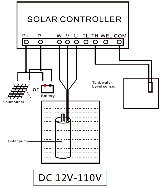
80w 12v Dc Solar Water Pump
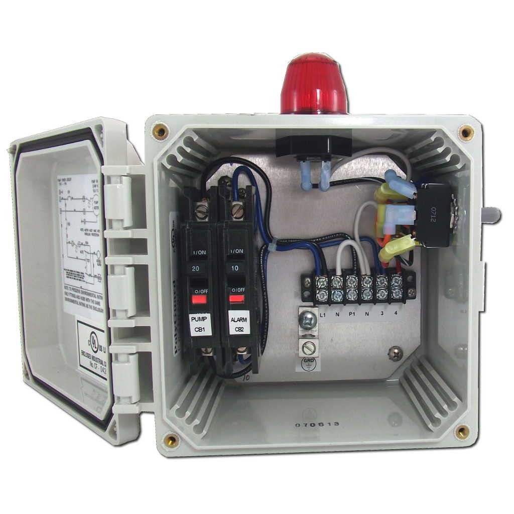
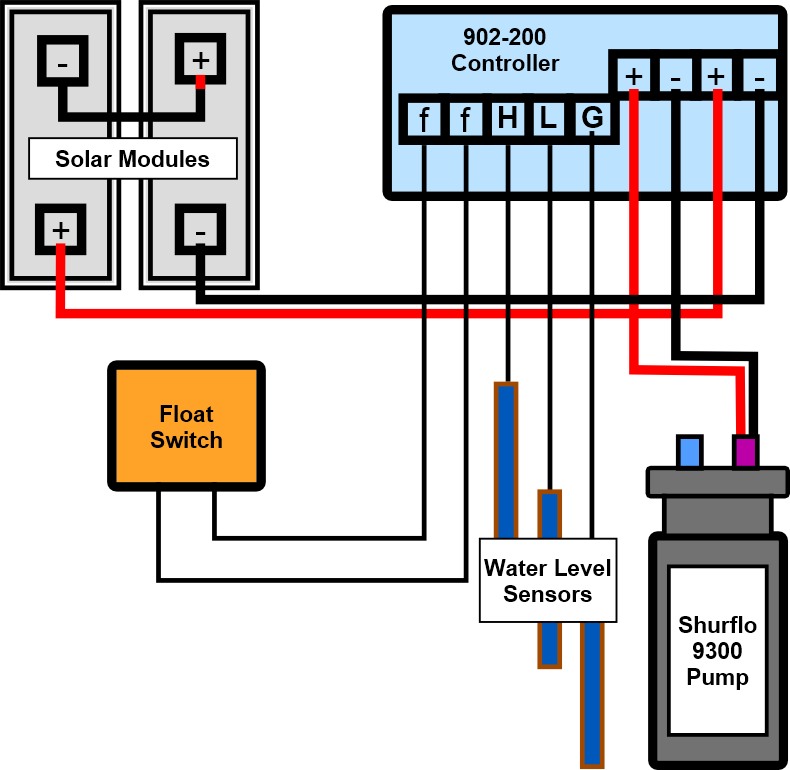
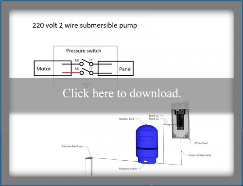
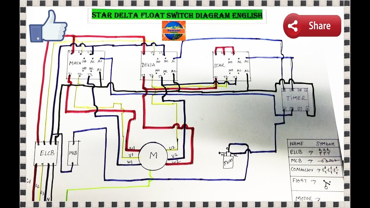
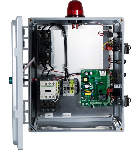
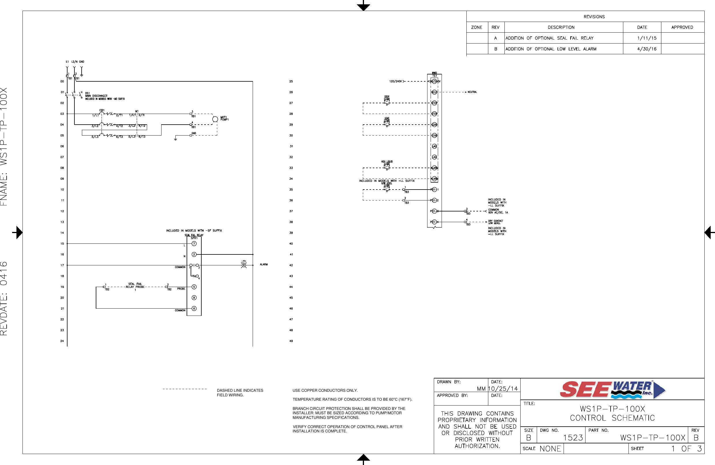
Water pump control panel wiring diagram. This article describes and identifies the switches controls and safety devices used on water tanks and water pumps such as the pump pressure control switch pump motor relays water tank relief valve water tank pressure gauge water tank air volume control and water tank air valve. A two wire single pole single throw float switchthe rising action of the float can either close ie turn on a normally open circuit or it can open turn off a normally closed circuitinstallation scenarios might include a normally open float switch turning on a pump to empty a tank control schematic 2 or a normally closed. Single phase wiring diagrams single phase wiring diagram for 05hp pumps with governor switch single phase wiring diagram with governor switch single phase wiring diagram without governor switch three phase wiring diagrams three phase 208v wiring diagram three phase 230v wiring diagram three phase 460v wiring diagram three phase 575v wiring diagram kb pump wiring diagrams kb pump 230v wiring. If it runs straight to the pressure switch it is a two wire. It shows the elements of the circuit as streamlined forms and the power and signal connections in between the devices. A gas tight seal see figure 1 is required to prevent corrosive septic gases from migrating into the ipc panel.
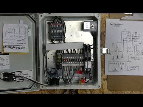
Connect the wiring in the splice box using water tight connectors. Single phase submersible motor starter wiring diagram explanation. If the conduit runs into a control box before continuing to the water pressure switch chances are you have a three wire pump. Here is the complete guide step by step. Wire the supply circuit to the panel. Well pump water pump controls.
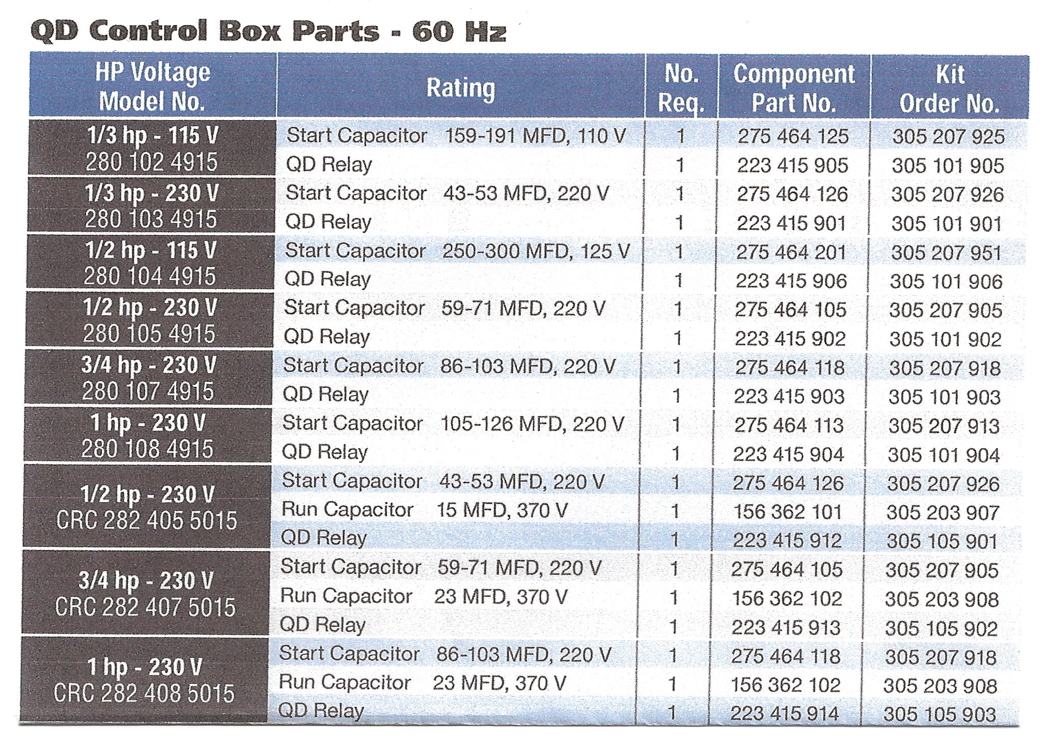
Lets start with the most basic float switch. The wiring connection of submersible pump control box is very simple. Connect pump wires to the ipc panel by carefully following the wiring diagram enclosed with the panel. Collection of submersible pump control box wiring diagram. Then provide the 240 circuit for the well pump from the panel and at least one 120 volt circuit for lighting and a gfi utility outlet. Single phase submersible pump control box wiring diagram 3 wire submersible pump wiring diagram in submersible pump control box we use a capacitor a resit able thermal overload and dpst switch double pole single throw.
It may be a better idea to install a larger conduit and pull in a larger 240 volt 3 wire circuit and ground to feed a sub panel. 3 wire submersible pump wiring diagram wellread. A submersible pump can be either two or three wire regardless of the voltage coming from the panel so start at your pump and follow the conduit back. Electrical guru is shoing in this video how the water tank is refilling automatically and its full system how its working full deffination for booster pump and submersible pump with panel. Single phase submersible pump starter wiring diagram gallery amazing single phase water pump control panel wiring diagram frieze. Installing a 240volt 3wire circuit for a well pump panel.
Gallery of Water Pump Control Panel Wiring Diagram