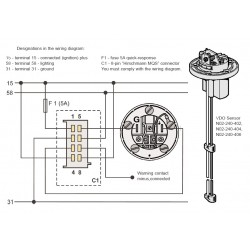
Connector set 8 pin a2c59510850. Viewline 85 mm tu00 0752 7407102 1 11 4 technische änderungen vorbehalten technical details subject to change tu00 0752 7407102 speedometer gb 30 terminal 30 steady state plus 12 v 15 terminal 15 connected ignition plus 58 terminal 58 lighting 31 terminal 31 ground designations in the wiring diagram.

88e1 Electric Meter Wiring Diagram Oil Wiring Resources
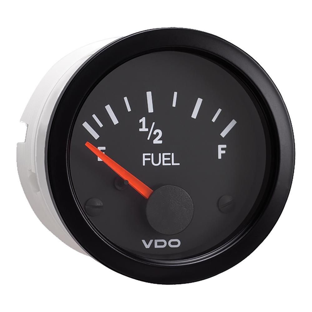
Vdo viewline wiring diagram. Viewline 52 mm temperature gauge pressure gauge rudder angel gauge trim gauge fuel gauge fresh water gauge for level type sensor tu00 0752 5207102 1 6 2 0611 gb procedures for installing vdo viewline instruments 1 2 before beginning turn off the ignition and remove the ignition key. Viewline 85 mm tu00 0752 6107102 1 6 3. You must comply with the wiring diagram. Viewline provides maximum freedom to customize the cockpit and is the natural choice for an attractive pcri e perof rmance ratio. Use the following connector to connect the instrument. On dip 0311 installation instructions.
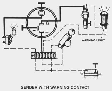
Procedures for installing vdo viewline instruments. Viewline 52 mm. Always disconnect battery ground before making any electrical connections. It shows the components of the circuit as simplified shapes and the facility and signal contacts between the devices. Fully sealed dual lens lifetime led lighting and warning indicators assure that viewline can easily withstand even open cab environments. Viewline 52mm wiring diagram 2014 viewline standard resistive gauges 52mm installation sheet 2014 viewline temperature gauges 1224 volt 2011 viewline temperature gauges 52mm 2008 vision cockpit outside temperature data sheet 2003 vision cockpit pressure temperature volt gauge data sheet 2003.
In creating the new vdo viewline series our engineers started with a clean sheet of paper to create an instrument line like no other in todays market. Introducing vdo viewline. Designations in the wiring diagram. The benefits of using viewline. 15 terminal 15 connected plus 12v 32v 31 terminal 31 ground c1 warning point control switching capacity 300 ma not short circuit proof. Our plug and play solution design concept.
Deviate from assembly or wiring diagram. Provisions of this warranty shall not apply to a vdo product used fora purpose for. Vdo viewline wiring diagram wiring diagram is a simplified satisfactory pictorial representation of an electrical circuit. Procedures for installing vdo viewline instruments. 30 terminal 30 steady state plus 1224 v 15 terminal 15 connected ignition plus 58 terminal 58 lighting 31 terminal 31 ground. Procedures for installing vdo viewline instruments.
Designations in the wiring diagram. Maximum precision and the deployment of pioneering technologies are equally important as ease of use and stylish design. Viewline instrument kit installation instructions tech support 1 800 265 1818.
Gallery of Vdo Viewline Wiring Diagram