This sensor is avail able from your auto parts dealer. It shows the components of the circuit as simplified shapes and the facility and signal contacts between the devices.

Vdo 3 3 8 In Viewline Onyx 3 000 Rpm Programmable Tachometer 12 24v A2c53218716 S
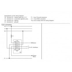
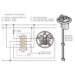
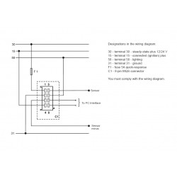
Vdo viewline tachometer wiring diagram. 30 terminal 30 steady state plus 1224 v 15 terminal 15 connected ignition plus 58 terminal 58 lighting 31 terminal 31 ground. Viewline 85 mm tu00 0752 5807102 1 10 4 technische änderungen vorbehalten technical details subject to change tu00 0752 5807102 tachometer gb 30 terminal 30 steady state plus 12 v 15 terminal 15 connected ignition plus 58 terminal 58 lighting 31 terminal 31 ground designations in the wiring diagram. Viewline tachometer without lcd 12 startup setting the impulse number imp r switch 1 switch 2 switch 3 xxx 0 0 0. Viewline 52mm wiring diagram 2014 viewline standard resistive gauges 52mm installation sheet 2014 viewline temperature gauges 1224 volt 2011 viewline temperature gauges 52mm 2008 vision cockpit outside temperature data sheet 2003 vision cockpit pressure temperature volt gauge data sheet 2003. Viewline 85 mm. Part numbers forhe t vdo generator sensor is part 340 001vdos inductive sensor is part 340 020 1.
Designations in the wiring diagram. Vdo tachometer is not included. Designations in the wiring diagram. Vdo viewline wiring diagram wiring diagram is a simplified satisfactory pictorial representation of an electrical circuit. 8 pin connection f1 fuse 5a quick response c1 8 pin mqs connector. Viewline 52 mm.
Procedures for installing vdo viewline instruments. Procedures for installing vdo viewline instruments. The 3¹₈ 80 mm tachometer requires a hole diameter of 3¹₈. Refer to diagram b for dimensions.
Gallery of Vdo Viewline Tachometer Wiring Diagram