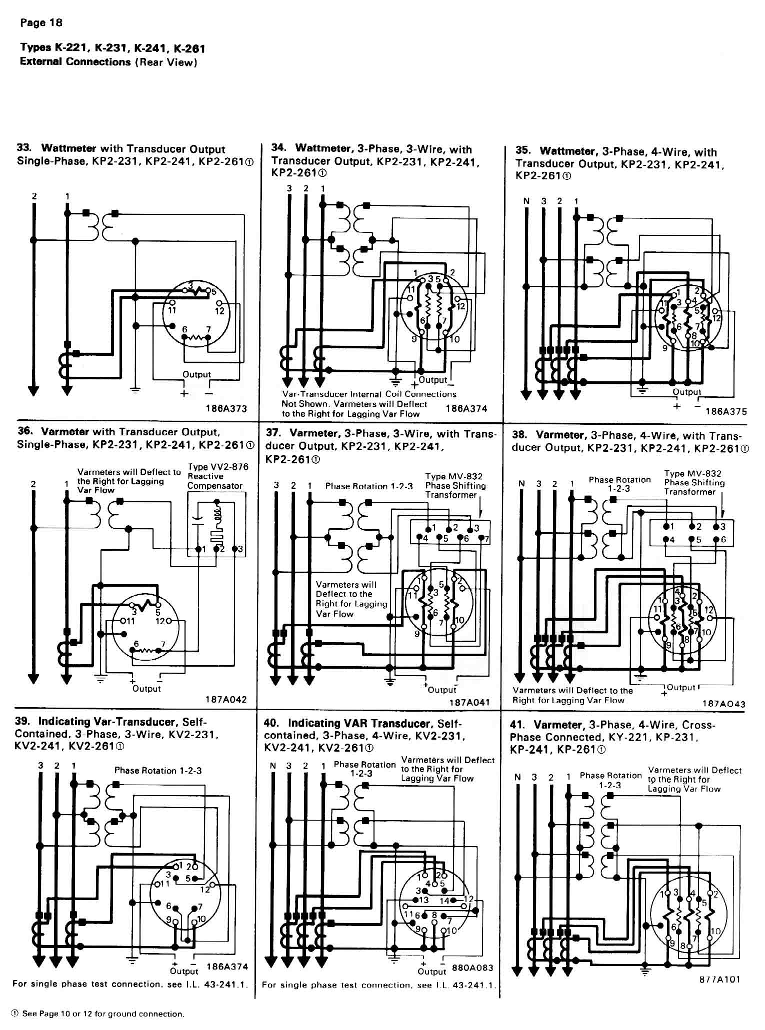
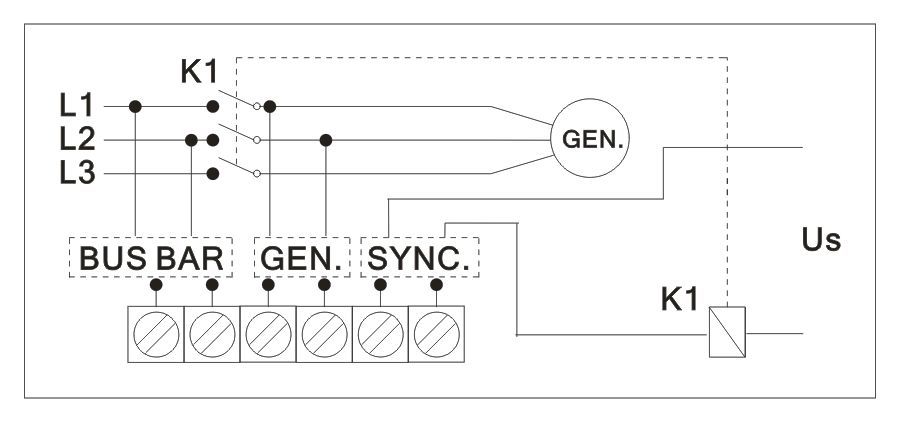
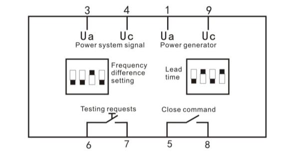
Inputs and outputs 3. Connection diagrams model 244 14a 360 led synchroscope models 244 14ldgh 360 led synchroscope and synchro check relay 12 6 low voltage directive this product complies with bsen61010 1 warning voltages dangerous to human life may be present at some of the terminals of this unit.

Ppt Synchronizing Powerpoint Presentation Free Download
Synchroscope wiring diagram. Tec tube 70188 views. Wiring on the switchboard should be completed before installing the instrument. Ensure all supplies are de. Supporting studs are provided for mounting the synchroscopes on the switchboard. Warnings legal information and notes to ce marking and ul listing this manual gives general guidelines on how to install and operate the csq 3. These instruments are practicall y unaffected by stray fields but it is advisable to keep transformers and wires carrying heavy.
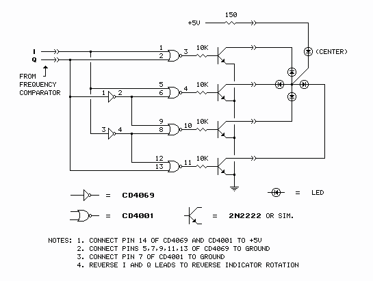
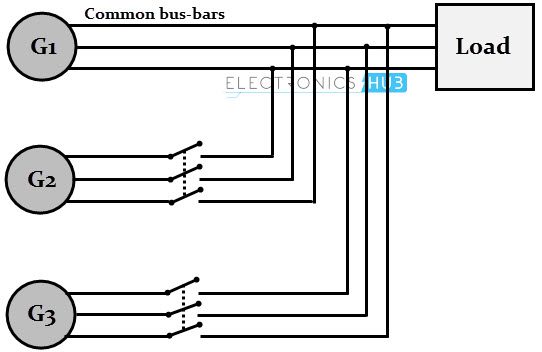
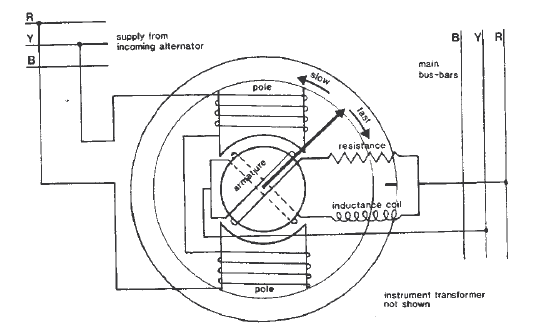
It shows the components of the circuit as simplified shapes and the gift and signal contacts amid the devices. Abo dabowsa supervisors prof. For two electrical systems to be synchronized both systems must operate at the same frequency and the phase angle between the systems must be zero and two polyphase systems must have the same phase sequence. Generators are synchronized with each other. Synchroscope wiring diagram wiring diagram is a simplified satisfactory pictorial representation of an electrical circuit. Design of an automatic synchronizing device for dual electrical generators based on can protocol by ahmad i.
User manual check synchroscope csq 3 4189340263l uk 1. Synchroscopes measure and display the frequency difference and phase angle between two power systems. Installing and operating the csq 3 implies work with dangerous currents and voltages. Mount the instrument in a level position. Declaration of conformity 9. Therefore this should only be done by qualified personnel.
In ac electrical power systems a synchroscope is a device that indicates the degree to which two systems generators or power networks are synchronized with each other. Wiring the unit 2. Dead bus enable 53 pre synchronization delay 6. Checking refrigerant charge for r 410a condensing units using sub cooling method duration. Connection diagrams model 244 14a 360 led synchroscope models 244 14ldgh 360 led synchroscope and synchro check relay 3 co common relay ratings single pole changeover 250v 5a ac. A synchroscope is a device that indicates the degree to which two systems eg.
Connection diagram table of contents. A synchroscope is used for indicating the appropriate moment for synchronization. Model 077 14a 360 led synchroscope 360 led synchroscope and synchro check relay models 077 14ldgh inst nc normally closed co common.
Gallery of Synchroscope Wiring Diagram