Thermostat wiring diagrams for heat pumps heat pump thermostat wire diagrams. Thermostat wiring and wire color chart thermostat wiring colors code.
230v Schematic Wiring Diagram Diagram Base Website Wiring
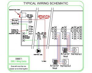
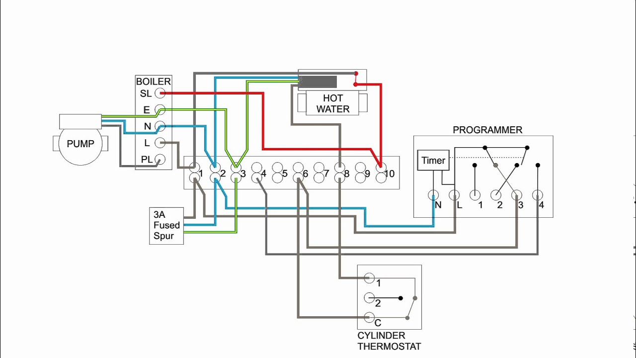
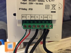
Neostat wiring diagram. Just need some help with some direction as to where i need to run cables from new stat to boiler please. Wiring diagrams the following diagrams show you how to install the nest thermostat on. Terminate the thermostat as shown in the diagrams on pages 28 31 of this booklet. 44 01254 669090 fax. Heatmiser uk ltd units 1 5 shadsworth business park mercer way blackburn lancashire bb1 2qu uk tel. Wiring diagrams wiring diagram neostat hw s plan timer no nc supply to neostat fused supply hot water valve to neostat hw stat hot water end switch boiler enable this product must only be installed by a qualified electrician and comply with local installation regulations.
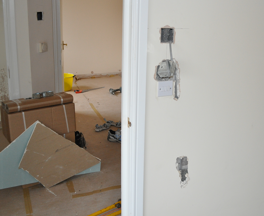
Heat pumps are different than air conditioners because a heat pump uses the process of refrigeration to heat and coolwhile an air conditioner uses the process of refrigeration to only cool the central air conditioner will usually be paired with a gas furnace an electric furnace or some other method of heating. It is a red wire and comes from the transformer usually located in the air handler for split systems but you may find the transformer in the condensing unit. Step 3 screw the thermostat back plate securely into the back box. For time clock wiring connections terminate as shown on page 38. For time clock wiring connections terminate as shown on page 38. Terminate the thermostat as shown in the diagrams on pages 28 31 of this booklet.
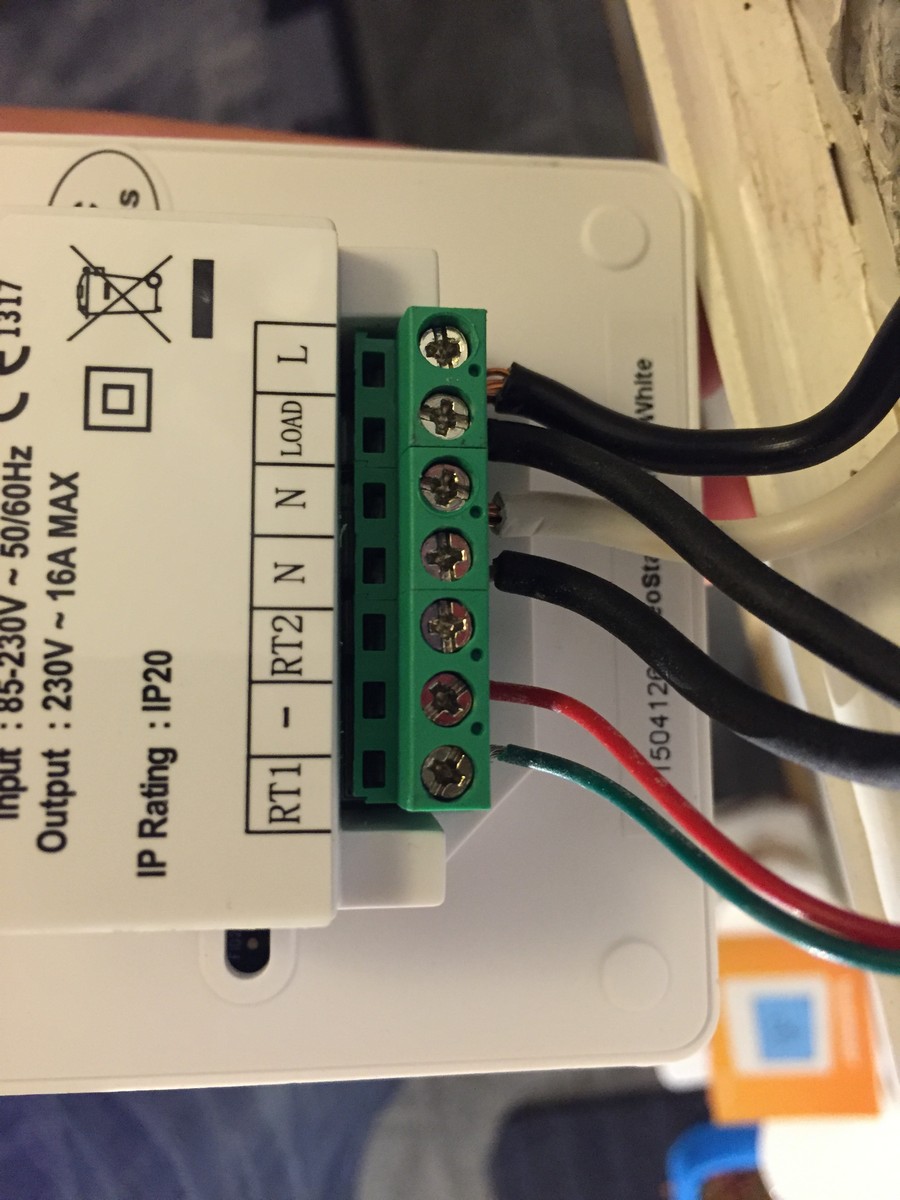
I would like to replace the honeywell thermostat with the below heatmiser neostat this is the wiring diagram i received with the unit. Currently the cable has 2 cores plus earth not connected running from the boiler to the stat however. Step 4 clip the front of the thermostat onto the back plate securing it in place with the retaining screw. R the r terminal is the power. Wiring diagram neostat hw mid position valve n n l a2 bl gr or supply to neostat heating neostat mid position valve hot water stat boiler enable fused supply to neostat hw timer stat hw l wh this product must only be installed by a qualified electrician and comply with local installation regulations. Color of wire and termination.
44 01254 669091 email. 230 v combi boilers page 20 low voltagedry contact combi boilers page 21 s plan page 22 y plan page 23 opentherm boiler page 24 district heating with electrical control valve page 25. W1hjmnesr w1hjmnesr wiring 1st fix heat pump system manifold wiring centres and thermostats neostat 230vac thermostats with wireless network view. The neostat v2 is designed to be flush mounted and requires a back box of 35mm.
Gallery of Neostat Wiring Diagram