When wiring your load to the ssr the wire is looped clockwise around the terminal so when the screw is tightened down it will draw the wire in tighter. Image adapted from solid state relay handbook with applications by anthony bishop.

Anacon Power Amp Controls 25a Leg 3 Phase Solid State Relay
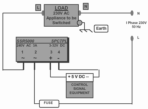
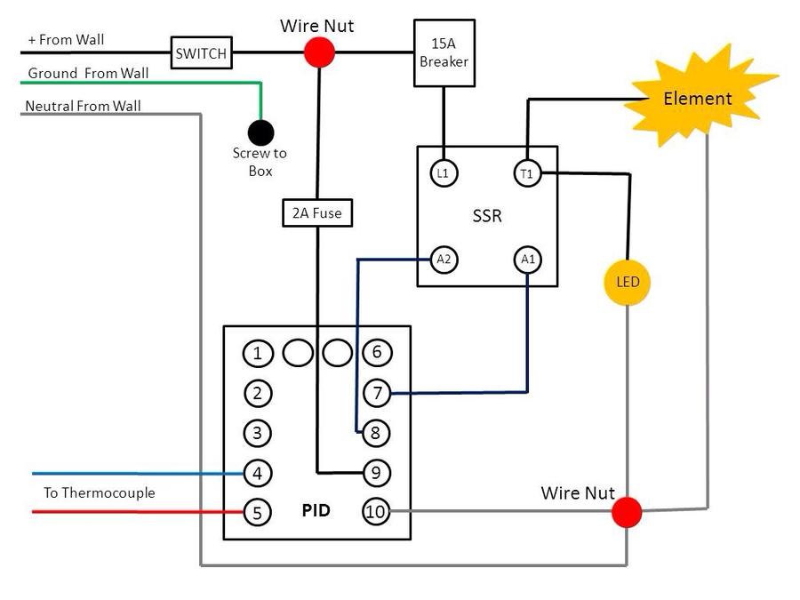
Ssr wiring diagram. Hybrid solid state relay ssr circuit diagram a solid state relay ssr is an on off control device in which the load current is conducted by one or more continue reading. Connect r positive terminal to the push button. Cooling fan diagram download. Variety of solid state relay wiring diagram. We recommend using wires up to 10 awg in size any larger and the screws will not have enough thread left to tighten down and they will strip. It shows the parts of the circuit as streamlined forms as well as the power as well as signal connections between the devices.
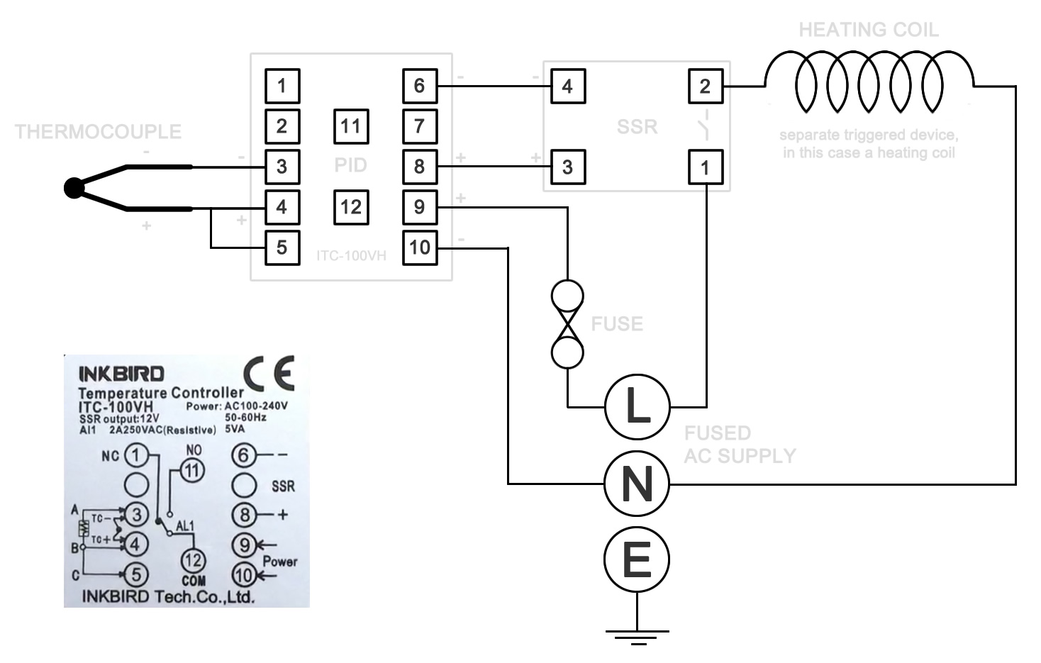
Auxiliary floor gauge diagram download. For much higher voltages an ssr is an excellent alternative when a regular switch cannot be used because of burn out under the current. Larger wires can be attached using a wiring lug. The diagram below shows how to wire a solid state relay. Form b type of ssr relay has normally closed load terminals. The diagram below shows an ssr relay capable of switching ac dc on separate terminals.
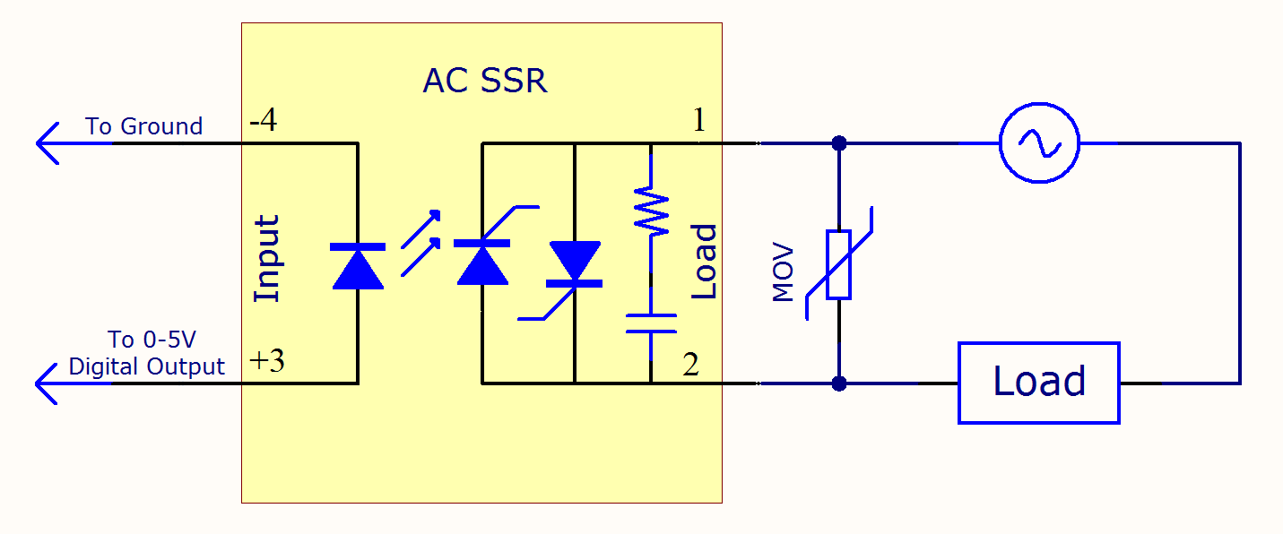
Please note that the diagram refers to dcdc type solid state relay ssr. Before installation and use please confirm whether the specifications such as input current input voltage output current output voltage and etc. Solid state relay dcdc. A wiring diagram is a simplified traditional pictorial depiction of an electrical circuit. Air bag diagram download. Daytime running light wiring diagram download.
The circuit wiring diagram of the industrial random conduction dc to ac solid state relay or industrial random fire dc to ac ssr is the same as the zero crossing dc to ac solid state relay. Dirt bike sr450s dirt bike circuit diagram 2017 sr250s dirt bike circuit diagram 2017 sr450s dirt bike wire diagram 2017. Form b or spst nc type ssr. In figure 9a when the scr is on the bridge structure provides a path for the current to flow no matter what the polarity of the power supply is. Technical resources for chevy ssr owners. Bose connector diagram download.
Solid state relay wiring diagram. A photodiode cell is used as a light receiver enhancement mosfets with common sources are used for switching the load circuit. An scr based ssr can be obtained by putting one scr in a bridge a or two scrs in inverse parallel b. Automatic shift interlock diagram download. Pit bike ssr pit bike wire diagram sr125 auto wire diagram lifan engine wire diagram sr125 6 wire cdi diagram.
Gallery of Ssr Wiring Diagram