To refitreplace a label or to repositionreplace a circuit breaker the front cover of the bep panel must be removed. A wiring diagram is a streamlined standard pictorial depiction of an electric circuit.
How To Draw Electrical Diagrams And Wiring Diagrams
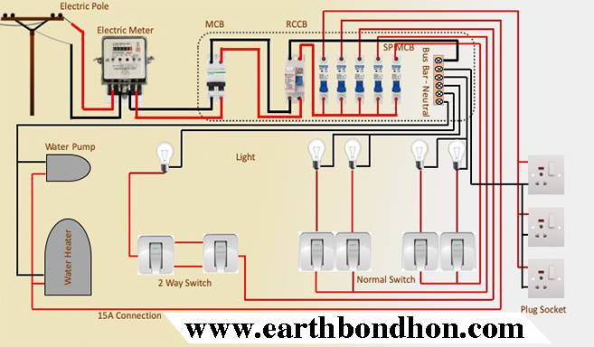
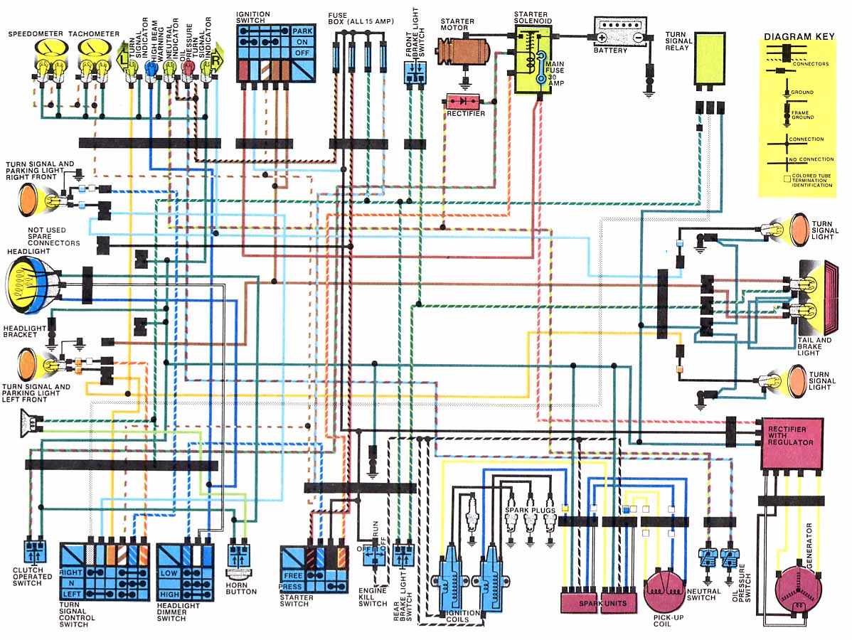
Circuit breaker panel wiring diagram pdf. It shows the components of the circuit as simplified shapes and the power as well as signal connections between the devices. Basics 13 valve limit switch legend. Basics 8 aov elementary block diagram. Wiring a breaker box is a highly technical skillknowing how it operates isnt. Basics 14 aov schematic with block included basics 15 wiring or connection. You may get along fine with longer runs.
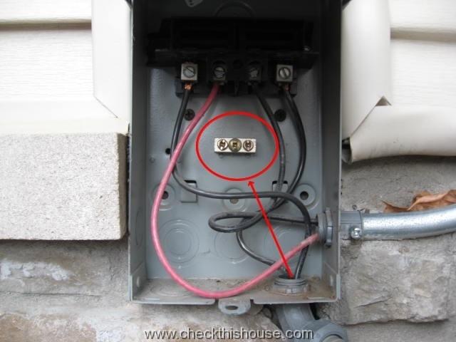
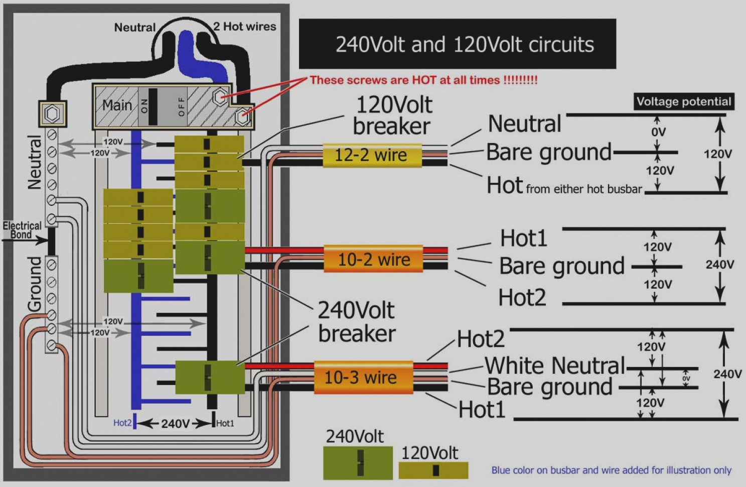
Basics 9 416 kv pump schematic. Take some of the mystery out of those wires and switches that lurk behind the door of your breaker box with this. This 30 amp 120 volt service will supply 3600 watts. Neutral bar in the panel. ł most branch circuit breakers can be mounted in any position line lugs ł all lugs suitable for 75 c copper or aluminum wires see fimain lugs and main circuit breaker ratingsfl on page 20 ł main lugs and main circuit breaker load centers have wire binding screw torque values on the wiring diagrams and circuit breaker labels neutral. Circuit breaker panel box wiring diagram.
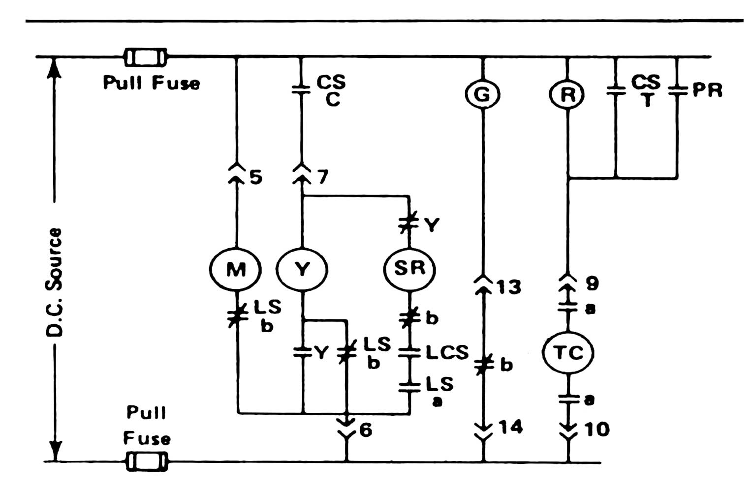
Labelling and replacing circuit breakers all bep panels come with a comprehensive set of self adhesive labels. A diagram that uses lines to represent the wires and symbols to represent components. Basics 11 mov schematic with block included basics 12 12 208 vac panel diagram. L3 circuit breaker stop start m ot t1 t2 t3 m m solid state overload relay 1ct m m motor 3ct to 120 v separate control ot is a switch that opens. This overview assumes that the electrical panel is installed on the wall of a utility area near where the main feeder wires come into the home and that all branch circuit wiring cables and conduit runs are already installed. This diagram illustrates some of the most common circuits found in a typical 200 amp circuit breaker service panel box.
In a new home construction or a rewiring project the last step will be connecting all the wires to the circuit breaker box which is what this article describes. Basics 10 480 v pump schematic. 15amp 20amp 30amp and 50amp as well as a gfci breaker and an isolated ground circuit. This is done by removing the two square drive screws at the rear of the plastic moulding covering the panel. 25 feet 10 50 feet 8 100 feet 6. Basics 7 416 kv 3 line diagram.
A diagram that represents the elements of a system using abstract graphic drawings or realistic pictures. Variety of square d breaker box wiring diagram. This page contains wiring diagrams for a service panel breaker box and circuit breakers including. Electrician circuit drawings and wiring diagrams youth explore trades skills 3 pictorial diagram. Wiring diagram book a1 15 b1 b2 16 18 b3 a2 b1 b3 15 supply voltage 16 18 l m h 2 levels b2 l1 f u 1 460 v f u 2 l2 l3 gnd h1 h3 h2 h4 f u 3 x1a f u 4 f u 5 x2a r power on optional x1 x2115 v. The bare or green wire is connected to the g screw or the u shaped prong and to the ground bar in the panel.
Recommended wire sizes for the 30 amp.
Gallery of Circuit Breaker Panel Wiring Diagram Pdf
/residential-circuit-breaker-panel-with-service-writing-184303809-5841f5ab5f9b5851e5701860.jpg)