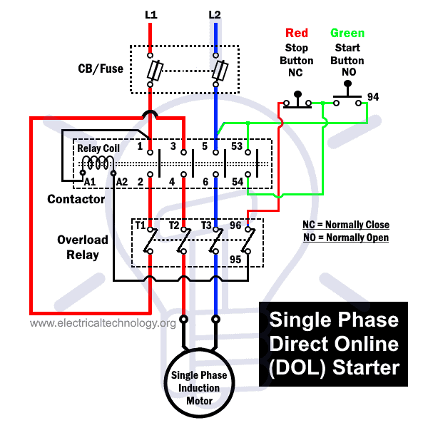
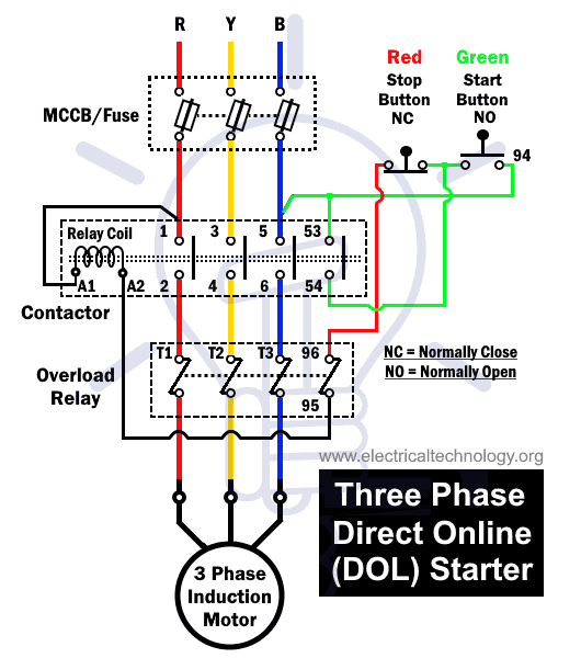
Please see the attached diagram for guidance. A direct online starter consits of two buttons a green button for starting and a red for stopping purpose of the motor.
Industrial Motor Control Starters Magnetic Motor Starter
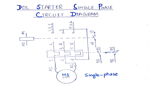
Single phase dol starter wiring diagram. It reveals the parts of the circuit as simplified shapes and the power and signal links between the gadgets. A wiring diagram is a simplified traditional photographic representation of an electric circuit. Normally it gets one phase constant from incoming supply voltage a1when coil gets second phase relay coil energizes and magnet of contactor produce electromagnetic field and due to this plunger of contactor will move and. Green and red or start and stop buttons control the contacts. This diagram illustrates possible wiring using a tesys d lc1d contactor and tesys lrd overload lrd and stop control is assumed to be by operation of the stop button on the overload. A single phase dol motor starter can be designed using the same components as shown in following diagram.
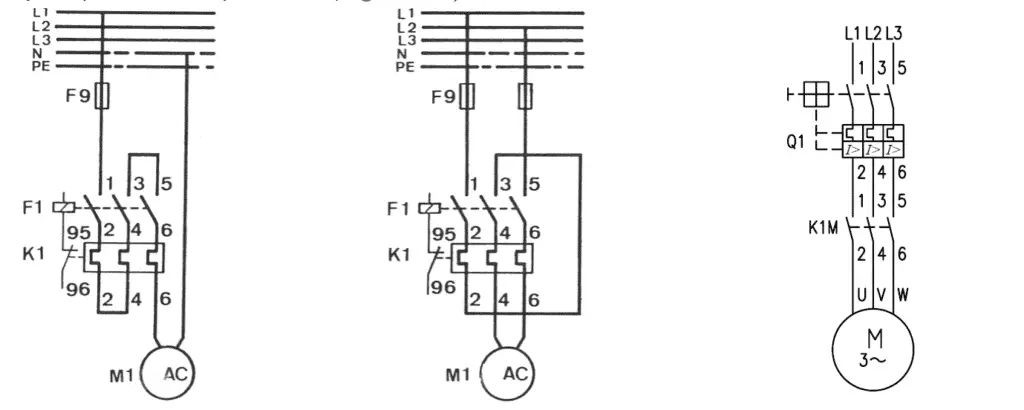
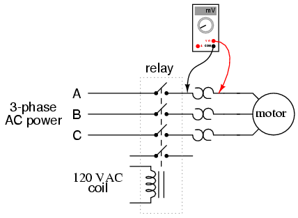
The diagram below shows the wiring for a single phase motor and the path through the contactor and overload. Collection of single phase motor starter wiring diagram. We have to use all 3 poles of the overload relay otherwise the imbalance due to the current flow in only 2 of them will cause unnecessary tripping. Working principle of dol starter. The main heart of dol starter is relay coil. The wiring diagram for a dol stater is shown below.
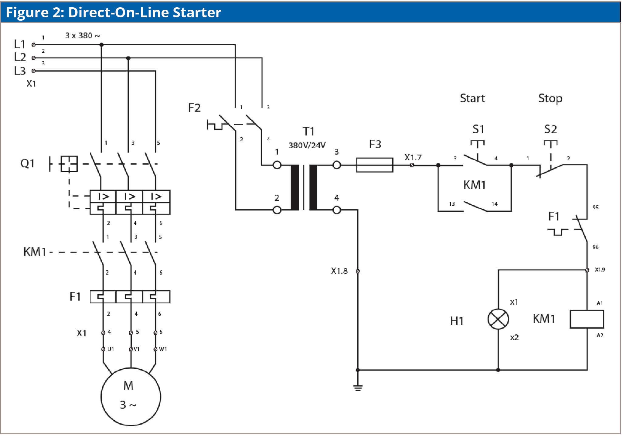
Direct on line starter wiring diagram. The dol starter comprises of an mccb or circuit breaker contactor and an overload relay for protection. These two buttons ie. Single phase dol starter wiring diagram.
Gallery of Single Phase Dol Starter Wiring Diagram