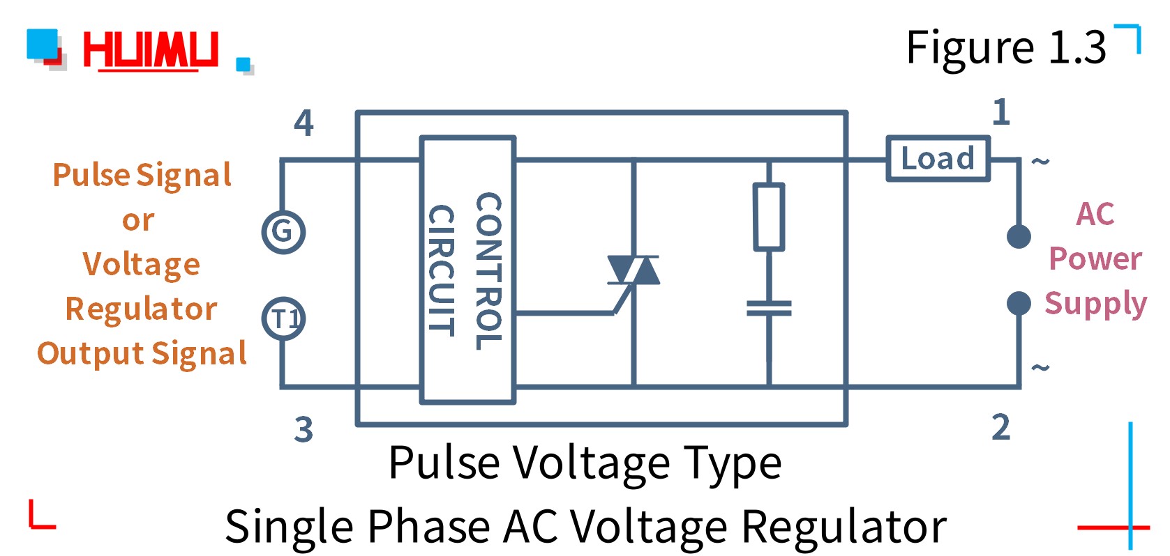
It has three external terminals anode gate and cathode and uses the alternative symbols of figure 1a and has the transistor equivalent circuit of figure 1bfigure 2 shows the basic way of using the scr as a dc switch with the anode positive relative to the cathode and the scr controlled via its gate. I live in the us and have the twist lock electrical plug 4 wire 30 amps 125250v nema l14 30p.
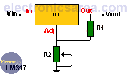
Lm317 Variable Voltage Regulator Circuit Diagram
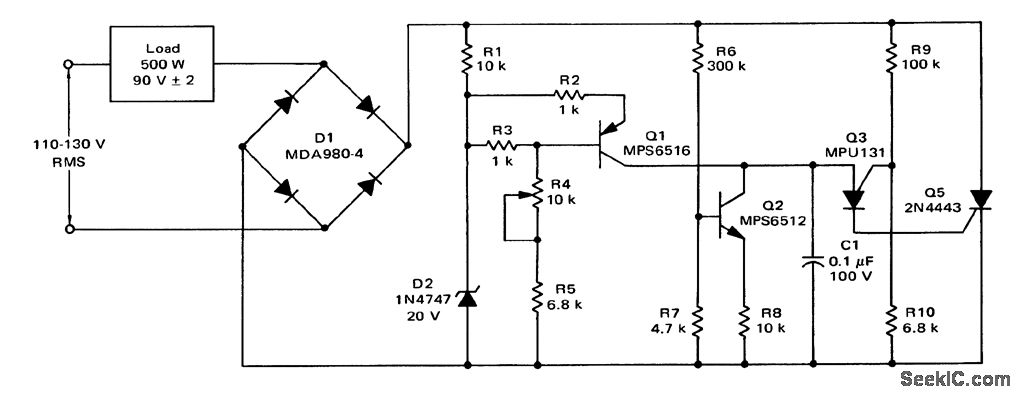
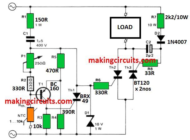
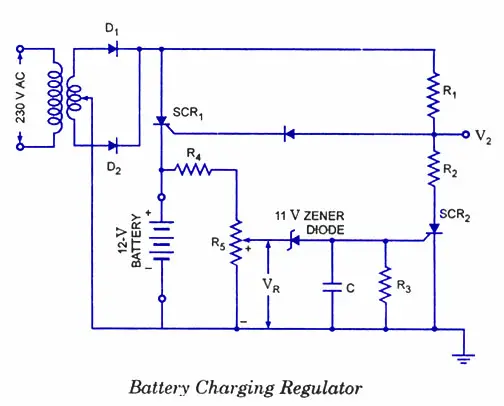
Scr voltage regulator wiring diagram. The firing circuit is a zero crossover type if it allows the scrs to gate only when the voltage across the scr is zero. Silicon controlled rectifier scr is a semiconductor rectifier that has the added. Currentpowervoltage 10000 watt240v 416a. I saw the following scr controller on ebay and am confused how one might do the wiring. A resistive load with scr control is diagrammed. R1 and r2 is adjusted to program the desired output voltage.
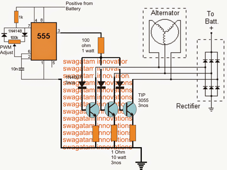
The proposed 3 phase motorcycle voltage regulator circuit for motorcycle may be witnessed in the diagram below. Just got an ic lm117 and 4 passive components. The 3 phase output from the alternator is sequentially applied across three power transistors which basically act like shunting devices for the alternator current. This is the most simple voltage regulator circuit diagram in our website. The lm338 has an output voltage range between 12v and 30v and it can deliver output current well over 5 ampere. For that kind of ampherage depending on the distance you are looking at 8 6ga wire.
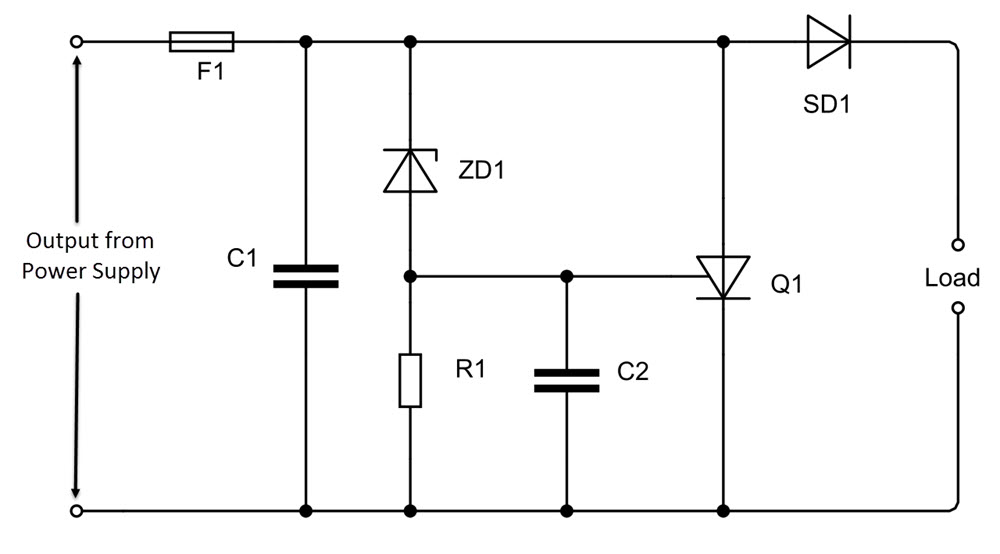
A typical application for an scr power regulator is shown in figure 2. Those terminals look like they are rated for a few amps and 16ga wire. An scr is a four layer pnpn silicon semiconductor device. It has 2 hots 1 ground and 1 neutral wire. 25 volts adjustable regulator using lm117. The schematic is rather easy to understand.
Theres a wiring diagram on the side of the picture.
Gallery of Scr Voltage Regulator Wiring Diagram