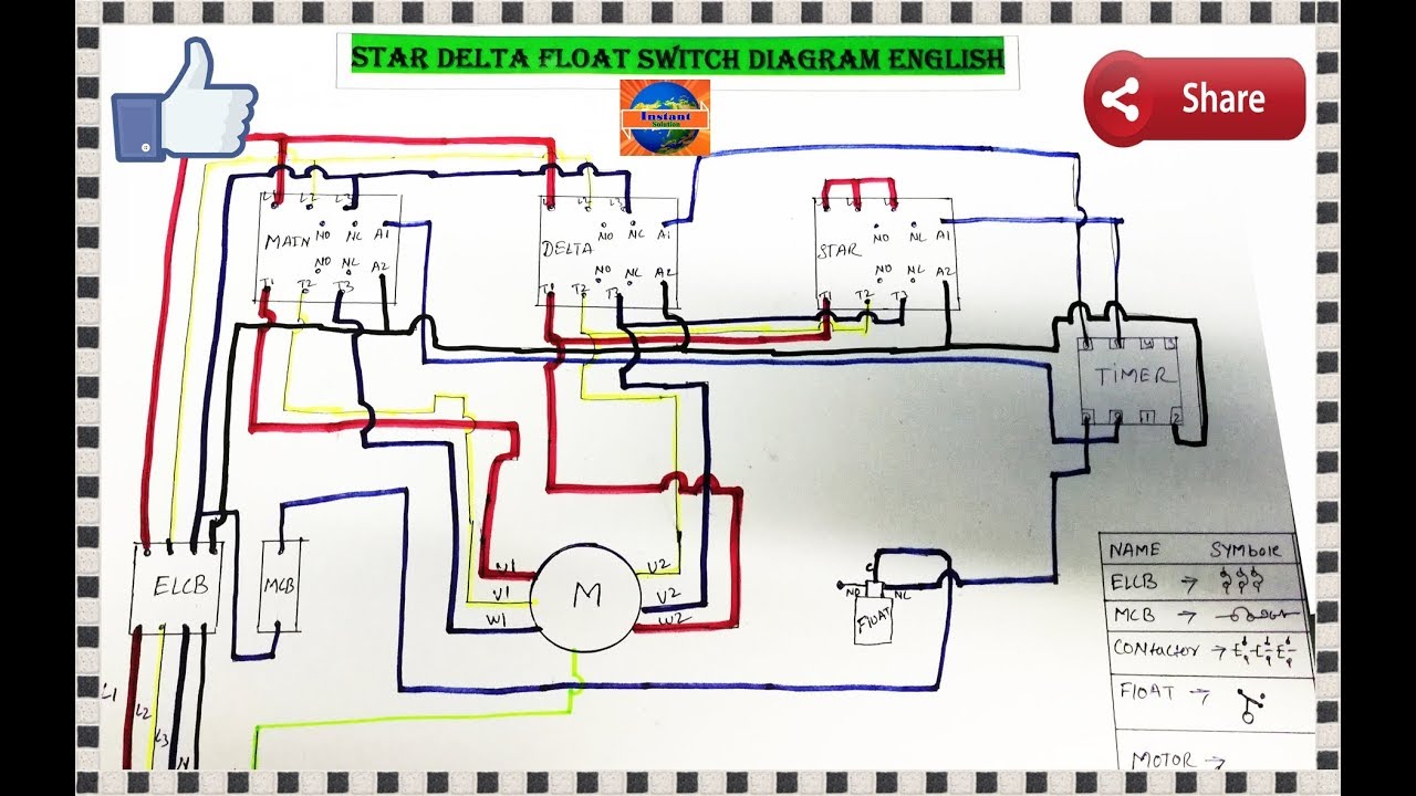
Wiring midrange pumps subcab 12 lead sensor cable alternative 1. Single phase submersible pump control box wiring diagram 3 wire submersible pump wiring diagram in submersible pump control box we use a capacitor a resit able thermal overload and dpst switch double pole single throw.

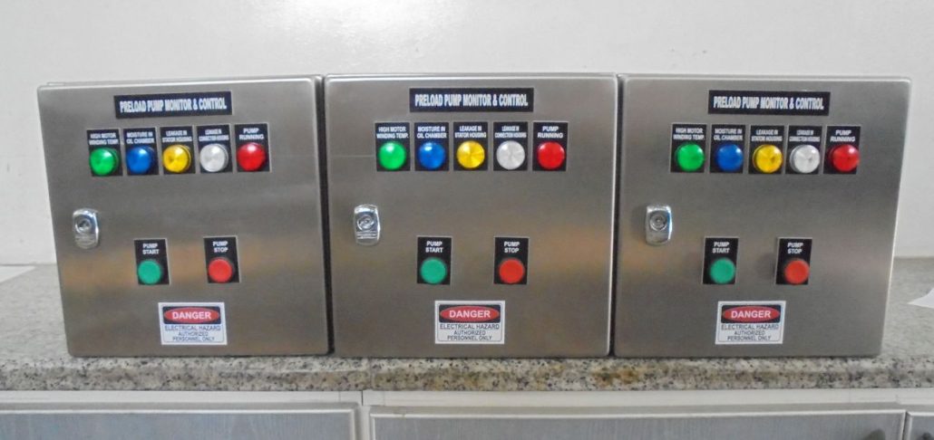
Mpc Type C Control Panel Twin Pump High Level And Pump Fail Alarm Single Phase
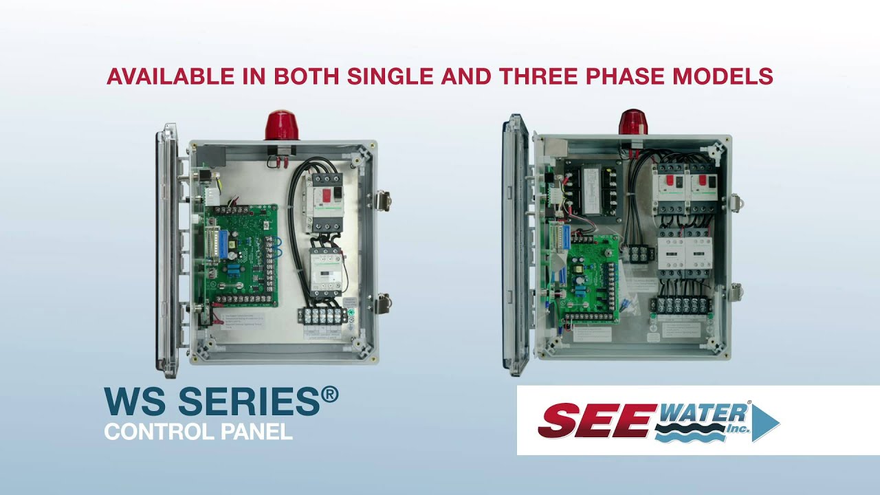
Flygt control panel wiring diagram. View online or download flygt mas 711 installation and operation manual. Flygt 2700 series flygt ds 2730 flygt ds 2730 is a electric submersible corrosion resistant sludge pump built to withstand the. Thermal switches with fls10. This photograph itt flygt pump wiring diagram flygt 3127 pump manual. Six basic sensor connections are possible. Thermal switches with fls the pilot cores in the pump can be connected to the panel in either polarity.
Six basic sensor connections are possible. The monitoring connections at the panel the minicas ii supervision relay is installed in the pump panel and simply plugs into an eleven pin relay base. Fls means either of leakage sensors flsfls10fls20fls30 depending on type of pump. Flygt bibo 2800 series flygt bibo 2870 the flygt bibo 2870 pump is designed like no other pump on the market. Thermal switches with fls the pilot cores in the pump can be connected to the panel in either polarity. A two wire single pole single throw float switchthe rising action of the float can either close ie turn on a normally open circuit or it can open turn off a normally closed circuitinstallation scenarios might include a normally open float switch turning on a pump to empty a tank control schematic 2 or a normally closed.
The wiring connection of submersible pump control box is very simple. The control panel should include a latching type circuit for over. Wiring diagram minicas llfus 120. Lets start with the most basic float switch. Communication port 37 38 for rs 485 is common to both pump memory and operator panel. The hydraulic design on the.
From the thousands of photographs on the internet concerning flygt pump wiring diagram we all selects the very best collections together with best quality only for you all and now this pictures is one of images libraries inside our greatest photos gallery with regards to flygt pump wiring diagrami hope you might enjoy it. Flygt to simultaneously supervise pump motor thermal switches and flygt pump leakage detectors fls stator. Wiring diagram minicas llfus 120. Keep me on the current site. Thermal switches with fls10. It looks like you are coming from thailand but the current site you have selected to visit is united statesdo you want to change sites.
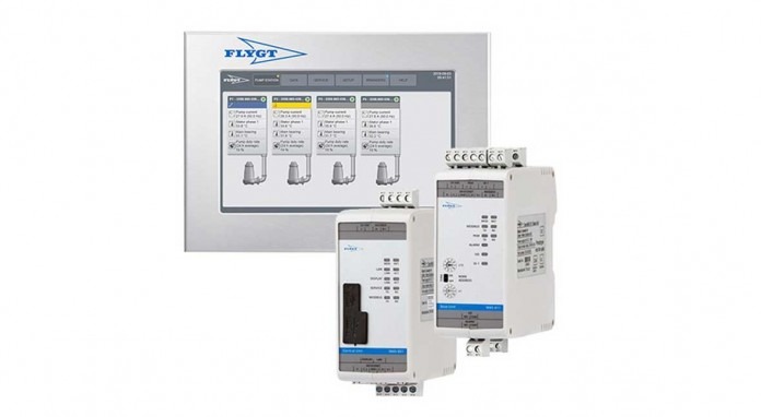
Water pump control unit controller measuring instruments. Here is the complete guide step by step. The monitoring connections at the panel the minicas ii supervision relay is installed in the pump panel and simply plugs into an eleven pin relay base. Terminal this is a wiring diagram of the sensor terminals section 2 used for a subcab 24 lead diagram sensor cable. Flygt mas 711 pdf user manuals.
Gallery of Flygt Control Panel Wiring Diagram