It shows the parts of the circuit as simplified shapes as well as the power as well as signal links between the tools. Each part should be set and linked to different parts in specific way.

Vga To Rca Wiring Diagram Vga To Yellow Rca Diy Wiring
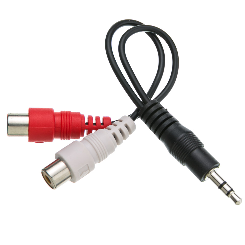
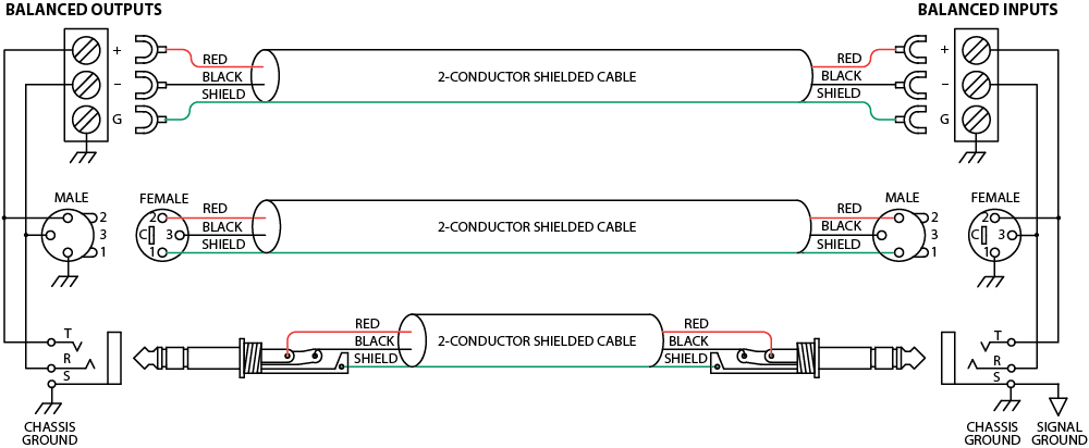
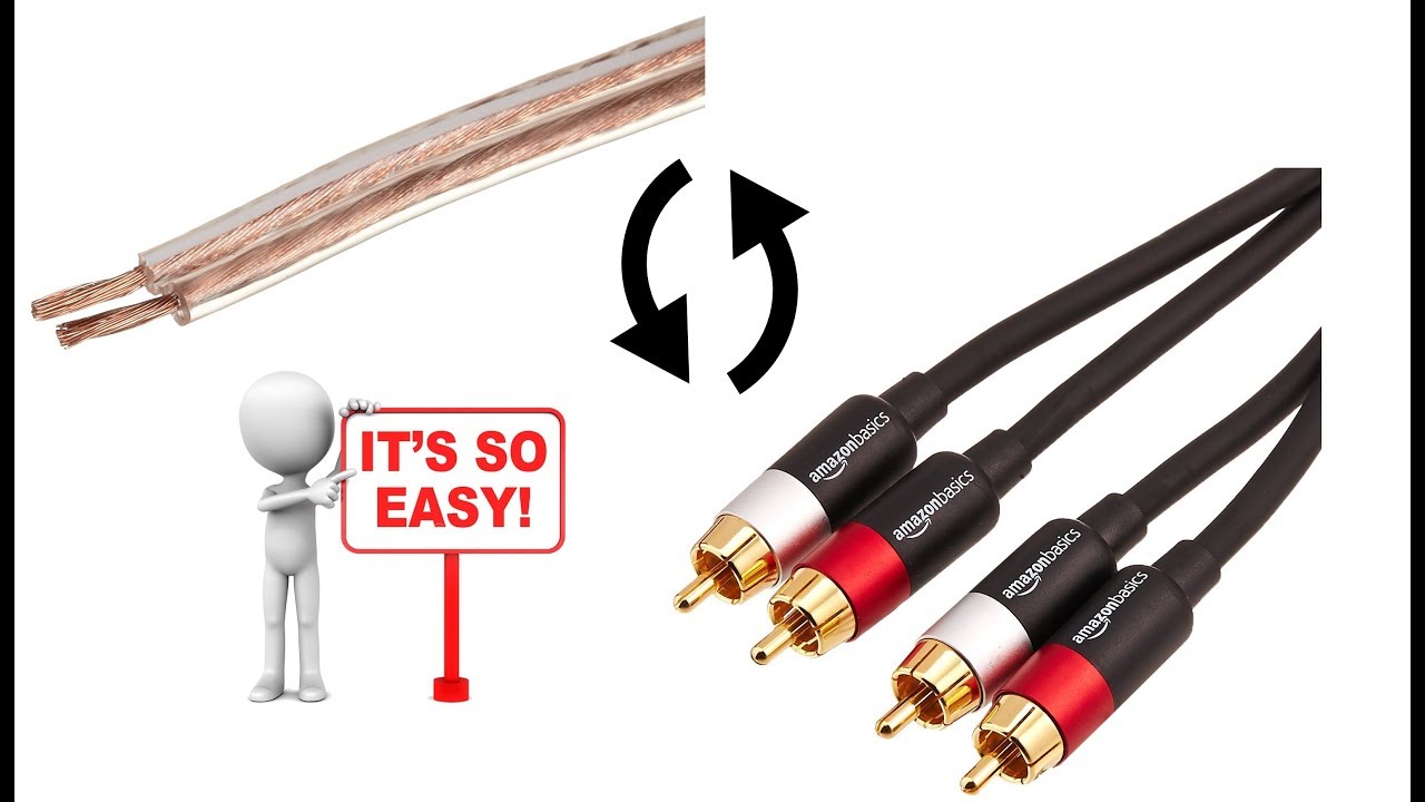
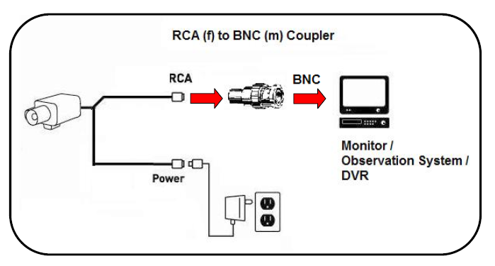
Rca plug wiring diagram. The benefit of connecting rca audio plug to speaker wires. Rca wiring diagram rca cable wiring diagram rca connector wiring diagram rca converter wiring diagram every electrical arrangement is composed of various different parts. An explanation and diagram showing how to wire an xlr cannon connector to r rca connectors. An additional third connector on an rca cable will be yellow for composite video. Assortment of hdmi to rca wiring diagram. A 3 pin xlr with a stereo signal can be split into left and right by wiring pin 2 of the xlr to the tip of one rca plug and pin 3 of the xlr to.
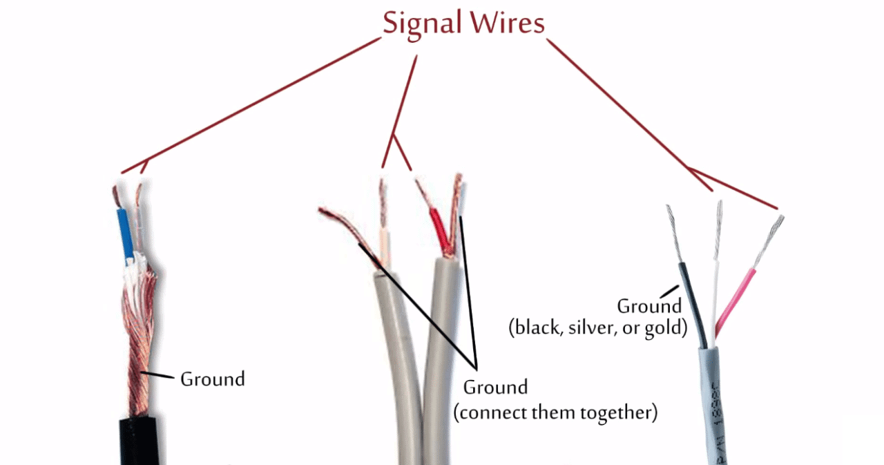
You will also see how the strands of the shield are gathered up and soldered to the outer conductor of the connector. Rca audio cables have two connectors. A wiring diagram is a streamlined standard pictorial representation of an electric circuit. Pin 2 rca tip. Rca to xlr wiring diagram thanks for visiting our site this is images about rca to xlr wiring diagram posted by maria nieto in rca category on may 09 2019. Hence by connecting rca plug to speaker wires you can use your speaker with the bare end to the devices.
You will also see the center conductor is not pulled tight. This produces an unbalanced audio cable. In the diagram below you will see the rca cable and connector. If not the structure wont work as it ought to be. But many sounds creating device takes the rca plug. How to convert speaker wires to rca plugs strip the insulation from both ends of the wire so that one half inch of bare wire is exposed step take one end of the speaker wire and slide the jacket for one of your rca plugs over the wire now insert the positive lead of the speaker wire into the center plug of the rca connector from the rear 3 pin rca jack wiring diagram circuit diagram maker 3 pin rca jack wiring diagram in addition more 292 also moreover usb.
Usb to rca cable wiring diagram usb to rca cable wiring diagram every electric structure consists of various diverse components. Pin 3 rca casing. Another variant connector is the stereo wired trs tip ring. 3 5 mm to rca wiring diagram wiring diagram name 3 5mm stereo audio cable to rca diagram wiring diagram expert a set of wiring diagrams may be required by the electrical inspection authority to implement attachment of the address to the public electrical supply system. Red right stereo and white or black for left stereo. Otherwise the arrangement will not work as it should be.
The typical connector for unbalanced audio is either rca 14 ts tip sleeve and 18 ts. Todays most of the speakers have bare end wire. You should also notice that they have no slack in them they are pulled tight. Rca plug to speaker wire diagram. Each part should be set and connected with different parts in specific manner. Typical rca cables will have two or three color coded connectors.
Connections are made by pushing the cables plug into the female jack on the device. Thus you need not buy a speaker with rca cable to use your device.
Gallery of Rca Plug Wiring Diagram