Leaks can lead to explosive accumulations of gas. The hmi 211 can be powered from pcc 1302 if within 500 feet 152 meters.
Powercommand 1 1 Control System Pdf Free Download
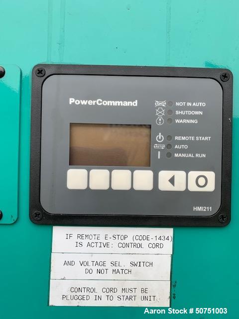
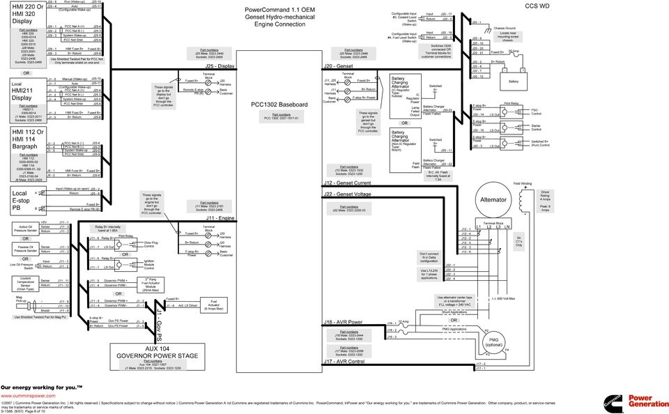
Power command hmi211 wiring diagram. Hmi211 cummins sudhir this is cummins hmi 211 controller in a diesel generator watch how to find fault by code and reset how to give power command star delta panel making httpsyoutube. The cummins hmi 211 connect series accessory remote display panel provides many of the same functions and control as the standard operator panel power command hmi211 mounted on the. Power command hmi211 wiring diagram. The wiring and harness connect the pcc1302 to the power command generator controller see the power command hmi211 wiring diagram in the instructions sheet. A051x877 issue 3 1. The wiring and harness connect the pcc1302 to the power command generator controller see the power command hmi211 wiring diagram in the instructions sheet.
Prevent leaks and the accumulation of gas. If greater than 500 feet power must come from an. See the wiring schematic in figure 5. Avital remote start wiring diagram. 2006 ford crown victoria police interceptor fuse box diagram. A rotten egg smell indicates a possible natural gas or propane leak.
Power generation with specific generator sets. Description 1 tb15 2 tb1 figure 4. Powercommand controller owners manual try the power command hmi wiring diagram and follow every detail in the picture. The cummins hmi 211 connect series accessory remote display panel provides many of the same functions and control as the standard operator panel power command hmi211 mounted on the. Wiring diagram for weil mclain boiler. Natural gas rises when released and can accumulate under hoods and inside housings and buildings.
Operator and installation manual remote network monitoring powercommand iwatch 100 english 12 2007 9000545 issue 3. Warn 8000 lb winch wiring diagram. Propane sinks when released and can accumulate inside housings and. 1746 ib32 wiring diagram. Connecting the hmi 211 remote no. In the event that this manual has been supplied in isolation please contact your authorized dealer.
Notice it is in the operators interest to read and understand all warnings and cautions contained in the documentation relevant to the generator set operation and daily maintenance. The powercommand control system is a power for this control system is derived from the generator set starting batteries. Wiring diagram on an ignitor system for at tappan gas stove. Pcc 1302 terminal blocks tb1 and tb15 6. It is power command hmi wiring diagram if you like to secure all of these fantastic pictures related to power command hmi wiring diagram click on save link to save the graphics to your pc. 1 j1 and j2 wiring connectors 2 p1 harness plug figure 3.
Gallery of Power Command Hmi211 Wiring Diagram