Pool Timer Wiring Diagram

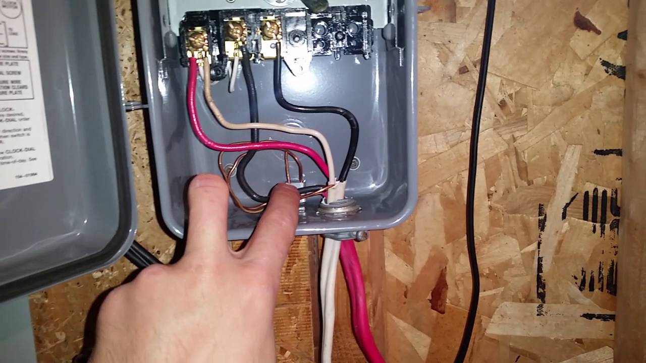
When wiring a single speed pool pump motor of either voltage 3 wires bring power from the breaker timer or switch and connect to the terminal board of the motor. To review a wiring diagram first you have to know just what fundamental components are consisted of in a wiring diagram and also which photographic signs are utilized to represent them.

T104 Timer Wiring Diagram Diagram Base Website Wiring Diagram

T104 Timer Wiring Diagram Diagram Base Website Wiring Diagram

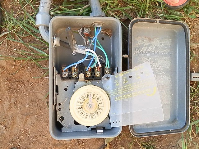
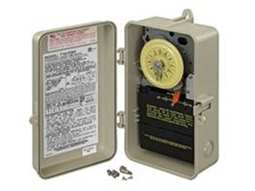
Pool timer wiring diagram. How to wire intermatic t104 and t103 t101 timers adorable pool pump whats wiring diagram. A wiring diagram is a sort of schematic which makes use of abstract pictorial icons to show all the interconnections of parts in a system. The common aspects in a wiring diagram are ground power supply cable and link outcome tools buttons resistors logic entrance lights etc. Open the intermatic timers cover. Pool pump timer wiring diagram wiring diagram is a simplified pleasing pictorial representation of an electrical circuit. Non conductive pool shells must have a 8 or larger solid copper wire buried 4 6 below finished grade with such bond wire placed from18 24 from the inside pool wall around the pool equipotential bonding that which starts and returns terminates at the pool pump.

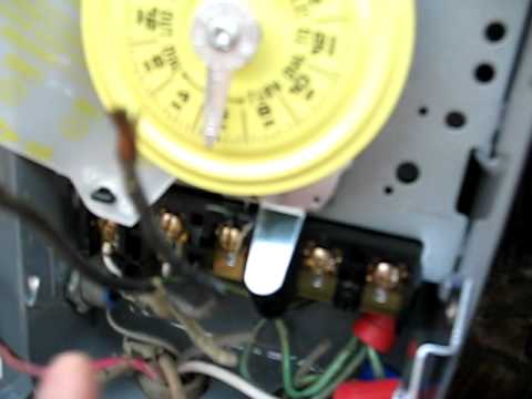
The schematic located on the inside of the pool timers lid shows the wire terminals positions their functions and labels them. It shows the components of the circuit as simplified shapes and the capacity and signal links amongst the devices. Lift or depress depending on the intermatic timer model the latch before opening the lid. Wiring instructions for an intermatic timer. Intermatic 240v timer wiring diagram t 104 control spdt 240v w freeze2 to intermatic pool timer wiring diagram. The green ground wire connects to the green ground screw and the other two power leads will connect to the two power terminals marked usually l1 and l2.

The wire terminals with the line designation connect to the wires coming from the circuit breaker and the wire. Turn off the circuit breaker to the appliance that the intermatic timer operates. Identify and locate the pool pump timers wire terminals using the timers schematic as a guide.

Gallery of Pool Timer Wiring Diagram

Intermatic Pool Timer Wiring Youtube
Download Now
Intermatic Pool Timer Wiring Youtube
Intermatic Pool Timer Wiring
Download Now
Intermatic Pool Timer Wiring
Dn 0076 Pool Control Panel Wiring Diagram Wiring Diagram
Download Now
Dn 0076 Pool Control Panel Wiring Diagram Wiring Diagram
Dual Pool Timer Wiring Diagram Solved Wiring Diagrama For
Download Now
Dual Pool Timer Wiring Diagram Solved Wiring Diagrama For
Zt 2659 Pump Wiring Diagram Together With Intermatic Pool
Download Now
Zt 2659 Pump Wiring Diagram Together With Intermatic Pool
How To Wire And Connect A Intermatic Pool Pump Timer T101r
Download Now
How To Wire And Connect A Intermatic Pool Pump Timer T101r
Intermatic Water Heater Timer Water Ionizer
Download Now
Intermatic Water Heater Timer Water Ionizer
Wg 1918 Pool Pump Timer Switch Wiring Diagram Need Help
Download Now
Wg 1918 Pool Pump Timer Switch Wiring Diagram Need Help
Bm 8875 Am Trying To Follow A Wiring Diagram For A Pool Pump
Download Now
Bm 8875 Am Trying To Follow A Wiring Diagram For A Pool Pump
Intermatic Digital Timer Wiring Diagram Bmw 2003 Rmnddesign Nl
Download Now
Intermatic Digital Timer Wiring Diagram Bmw 2003 Rmnddesign Nl
Wire Diagram For Sand Filter Pump Trouble Free Pool
Download Now
Wire Diagram For Sand Filter Pump Trouble Free Pool
How To Replace An Intermatic T101m 120v Pool Timer
Download Now
How To Replace An Intermatic T101m 120v Pool Timer
How To Wire T103 Timer
Download Now
How To Wire T103 Timer
How To Install Wifi Pool Pump Timer With Wion Smart Box Comic Cons 2020 Dates
Download Now
How To Install Wifi Pool Pump Timer With Wion Smart Box Comic Cons 2020 Dates
How To Wire Intermatic T104 And T103 And T101 Timers
Download Now
How To Wire Intermatic T104 And T103 And T101 Timers
Intermatic T104 Electromechanical Timer 208 277 V 40 A 1 23 Hr 1 12 Cycles Per Day Gray
Download Now
Intermatic T104 Electromechanical Timer 208 277 V 40 A 1 23 Hr 1 12 Cycles Per Day Gray
Wiring Diagram For T104 Pool Timer How To Wire Intermatic
Download Now
Wiring Diagram For T104 Pool Timer How To Wire Intermatic
Intermatic Photo Control Wiring Diagram Carh 2003 Rmnddesign Nl
Download Now
Intermatic Photo Control Wiring Diagram Carh 2003 Rmnddesign Nl
How To Install An Intermatic T104 Timer Inyopools Com
Download Now
How To Install An Intermatic T104 Timer Inyopools Com