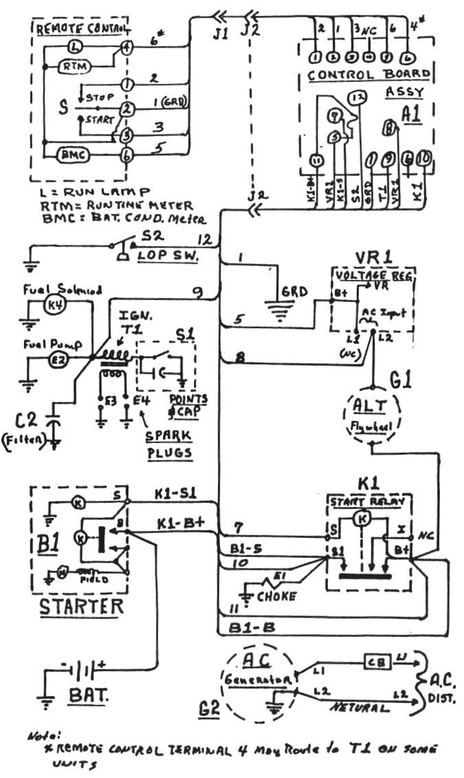
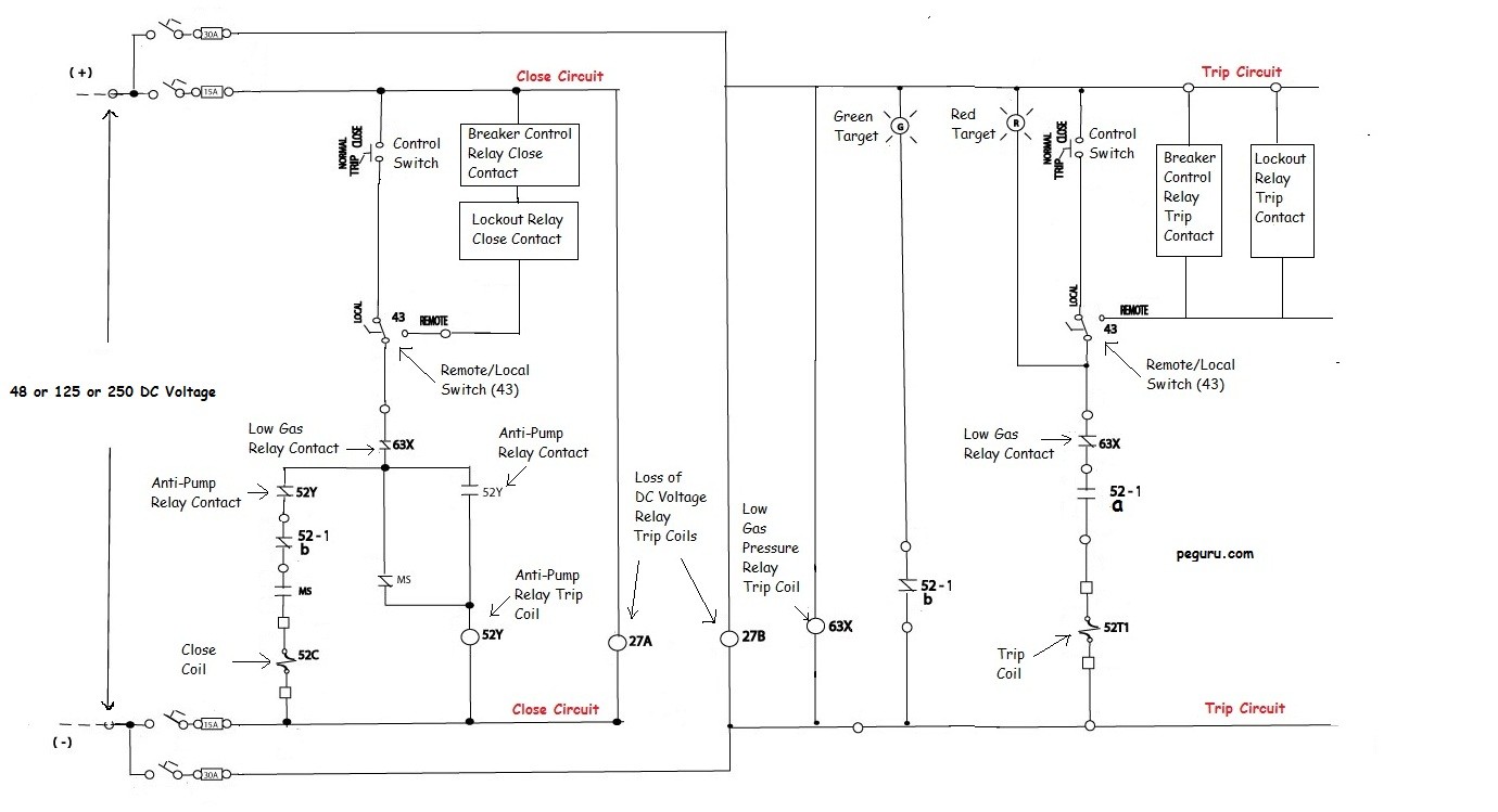
In the remote position the start voltage is supplied by the green wire from the wrsc module. Local remote selector switch real life indrajit pal.
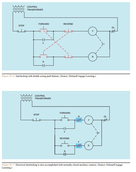
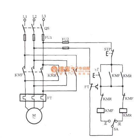
Forward Re Verse Control Developing A Wiring Diagram And
Local remote switch wiring diagram. Every remote start wiring diagram contains information from other people who own the same car as you. When wiring this switch you can choose if youd like to illuminate it because of the independent lamp attached to terminals 8 and 7. Typical wiring diagrams for push button control stations 3 genera information at each circuit is illustrated with a control circuit continued schematic or line diagram and a control station wiring diagram. How to do rotary cam changeover switch wiring connection in urdu and. Wiring diagrams do not show the. Wiring diagrams m c w bulletin 600 bulletin 600 manual starting switches are designed for starting and protecting small ac and dc motors rated at 1 hp or less where undervoltage protection is not needed.
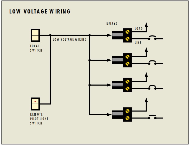
L the schematic or line diagram includes all the components of the control circuit and indicates their function. If you want to install a new remote car starter youll love. The wiring diagram to the right will show how to wire and power this 12v 20amp on off on 3 way carling contura rocker switch. A wiring diagram is a simplified traditional photographic depiction of an electric circuit. Assortment of pump control panel wiring diagram schematic. Local remote multiple point control wiring diagram in hindi.
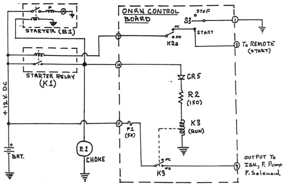
Be sure magneto switch is in the on position and the idle control economy switch is set to off when the wrcs switch is set to the remote position. Wiring diagrams for lcs products for onoff control proportional control basic onoff wiring diagram lcs la full proportional control wiring. A remotelocal control selector switch can often be situated in proximity to the controlled plant ie. Find the remote starter wiring diagram you need to install your car starter and save time. The neutral from the source is spliced through to the switch box using the white wire and in this diagram the white wire is capped with a wire nut. Local to the equipment and allow an operator to take control locally and avoid the need to interact or accept remote supervisory commands.
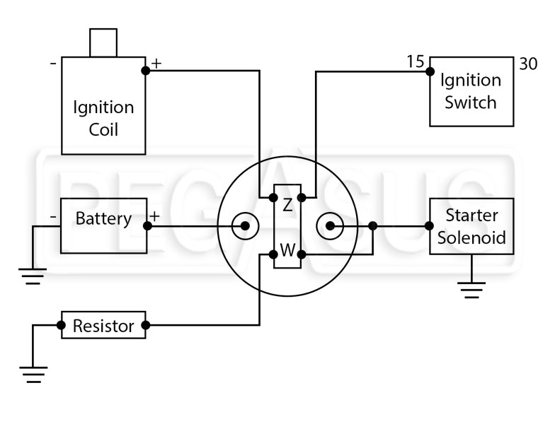
Scroll down and find the car start wire guide you need. Or these terminals can be ignored for non backlit switch banks. Suggested wiring diagram when in the local position the key switch is used to start the engine. In this updated diagram 3 wire cable runs between the receptacle and switch and the red cable wire is used to carry the hot source to the switch. This unit has a remoteofflocal switch a position potentiometer which generates a full 4 20 ma signal to position the actuator in local mode openclose indicator lights and dual digital displays. It shows the parts of the circuit as simplified shapes as well as the power as well as signal links between the devices.
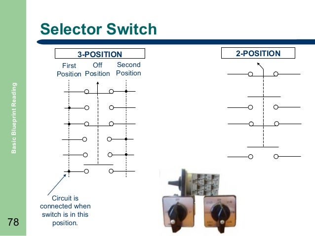
They are operated by a toggle lever mounted on the front of the switch.
Gallery of Local Remote Switch Wiring Diagram