Also will need a toolbox so that i can install the electronics and the pump in a portable manner. Welcome to the improved perfect power wiring diagrams.
Sump Pump Float Switch Cord
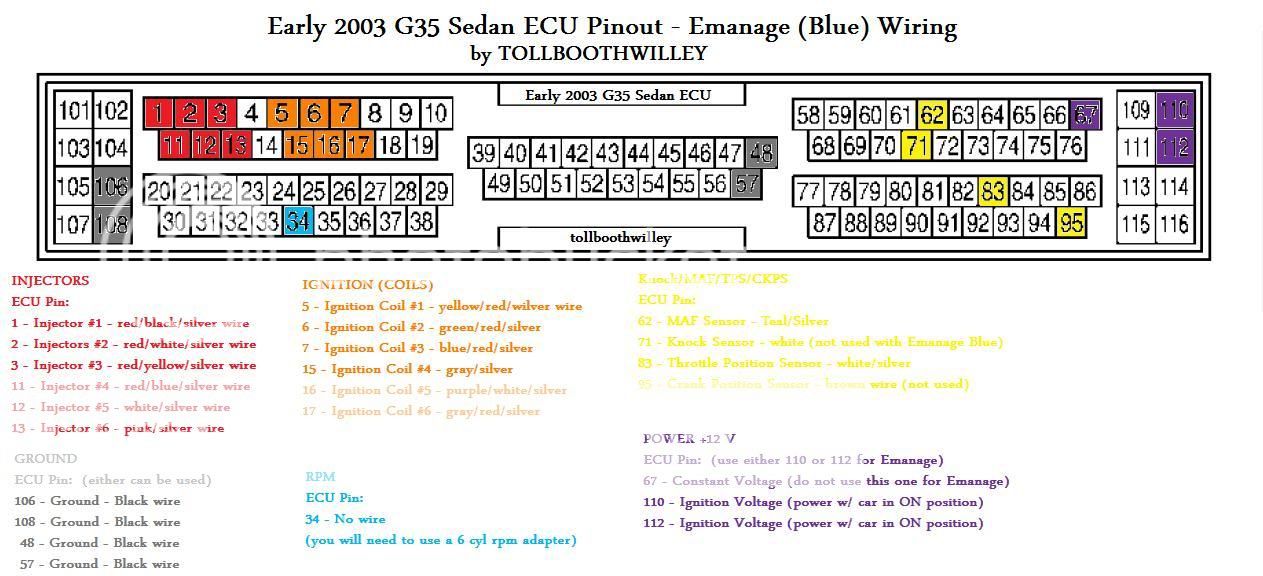
Piggyback wiring diagram. Select below the perfect power piggy back product smt6 smt7 smt8 smt8 l smt8 t to find the associated wiring diagrams then select from the list of vehicle manufacturers that we have created wiring diagrams for. These wiring diagrams are the electrical connections between our piggy back units and your existing ecu in your car. Do not use the method described below for 230v pumps. Still need to order the heater for the tube a float switch and a piggyback cord if someone is nice enough to respond to this post and provide advice as to whether or not that will work. We recommend using a piggy back float switch or control panel to operate 230v pumps. If only 1 wire is a source then everything needs to branch off of it.
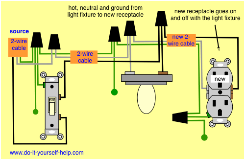
As long as the maximum amount of amperage per circuit is observed this technique is safe. Perfect power piggy back wiring diagrams. Piggybacking is possible because of the four wiring terminals found on each outlet and is a standard process when wiring a home. Piggybacking is a wiring technique that jumps from one junction box to another. Hi folks ive done replacing switch with dimmers replaced ceiling fans and other simple electrical stuff but this one is not as straight forward. Then the hard partfiguring out how to wire it all up.
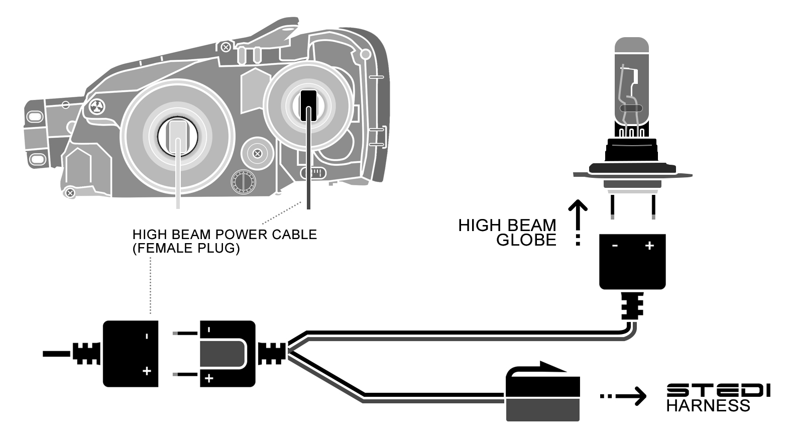
Our piggy back units will be working in harmony with your engine control unit ecu to provide the ultimate harmonious performance and fuel consumption from your engine. Vehicle specific piggyback adaptor as displayed in the below diagram the vehicle specific piggyback adaptors do not plug to the vehicles high beam globe but instead the main power plug for the headlight as a whole. Hot neutral and ground. The information below refers to 115v pumps and wiring. In 115v wiring you are dealing with 3 legs. Your diagram does not make sense.
Gallery of Piggyback Wiring Diagram