It reveals the elements of the circuit as streamlined forms as well as the power as well as signal connections between the gadgets. Posted on march 14 2018.

Floor Heat Floor Heat Thermostat Wiring
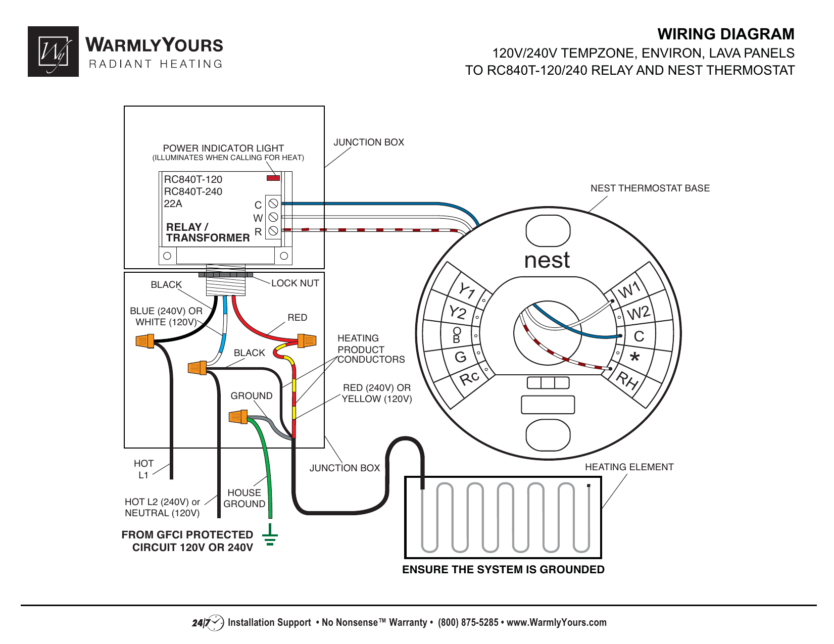
Aube thermostat wiring diagram. 2 pole ac contactor wiring diagram 2 l t12 ballast wiring diagram 2 door chime wiring schematic. Aube rc840t 240 wiring diagram wiring diagram is a simplified conventional pictorial representation of an electrical circuit. Nest thermostat wiring diagram with aube transformer and relay for swamp cooler technology creates a much better life and its true. A wiring diagram is a simplified standard pictorial representation of an electric circuit. The basic heat ac system thermostat typically utilizes only 5 terminals. Sophisticated gadgets and devices also come to boost your home using technologies one of which is nest thermostat.
Aube rc840t 240 wiring diagram. Variety of aube rc840t 240 wiring diagram. Thermostat aube technologies econnect wireless thermostat kit ta7210 system installation manual. Connect the heating relay to terminal w. Txrx 2 ac144 02 remote temperature interface see 14 ac144 02 gnd 3 figure 1. Variety of aube rc840t 240 wiring diagram.
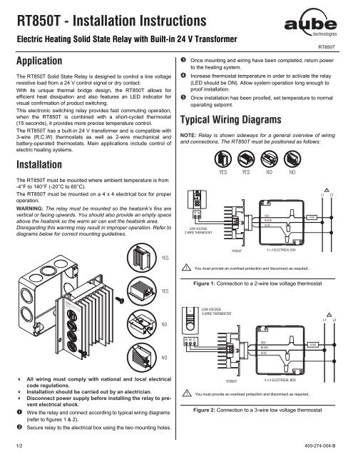
Wiring diagrams 15 c 162 3 w onnect the labelled wires to the thermostat ire heating system with fan control 1. A wiring diagram is a streamlined standard pictorial representation of an electrical circuit. It shows the components of the circuit as simplified shapes and also the power and signal links between the devices. It shows the components of the circuit as simplified shapes and the capability and signal contacts amid the devices. Assortment of aube rc840t 240 wiring diagram. Aube rc840t 240 wiring diagram sample.
A wiring diagram is a streamlined conventional photographic representation of an electrical circuit. Diagram shown in section 16. Wireless thermostat kit 52 pages. It shows the parts of the circuit as streamlined forms as well as the power and signal connections in between the devices. March 6 2019 by larry a. Rc red wire power 24 vac rh or 4 red wire jumpered power 24 vac w white wire for heating enable y yellow wire for cooling enable g green wire controls fan on auto the diagram shows how the wiring works.
Typical wiring diagram model shown th144 3h2c th144 400 144 000 c 2008 02 08. Connect the system wires to the thermostat terminals according to the wiring 1.
Gallery of Aube Thermostat Wiring Diagram