This is just a quick video of final wiring and testing the peco pl 10e point motor with a stapleton 751d cdu. Connect this unit to the 16v ac supply on your transformer.
Point Control 2
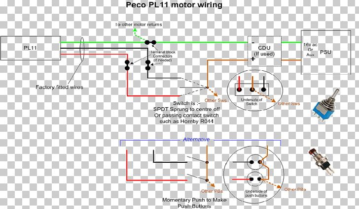
Peco cdu wiring diagram. For seeps pm1 pm2 i would use the centre diagram wire the positive to the centre pole of a two way on off on flick switch then each side of the switch to the contacts on the point motor see diagram below you can run multiple switches from the same cdu i think mine runs 16 points but will only power four switches. Testing this with led lights on an n scale electrofrog turnout to determine power. Basic point wiring diagram with hornby r044 passing contact switch. Peco code 100 electrofrog 3 way turnout bottom the red arrow shows the connection between two of the frogs. Wiring point work special track conditions for dc or dcc 1. Wiring blocksignalling capacitor discharge unit cdu and points position indicator ppi to leds.
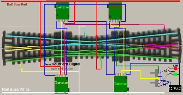
We also cover this subject in detail in another advice chapter advice 2making peco better. Peco pl 10e point motor installation duration. Peco pl 13 accessory switches fit directly onto hornby point motors without modification and can be used for frog switching on live frog points such as peco electrofrogs points operated signalling to provide feedback for automatic control or just to indicate on a control panel that the point has. The basics of wiring a turnout correctly. Pennyhill junction 31267 views. Wiring diagram for the peco 3 way electrofrog please note that in order to make the wiring diagram as neat and simple as possible the position of the tortoises are reversed underneath the turnout.
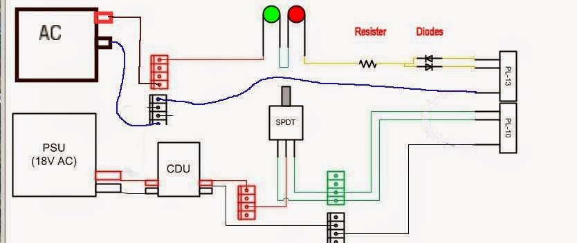
For use with all solenoid motors eg. Peco cdu wiring diagram 26112018 26112018 3 comments on peco cdu wiring diagram i am in the process of wiring the pointwork for my fiddle yard and due for a couple of the sidings i will need to throw 7 points simultaneously mixture of peco and hornby sorry i cant be of more help other than to tell you to look for cdus. Diagram shows three point motors powered by a cdu each point motor momentary toggle switches are spring loaded switches. The capacitor stores up power and discharges a kick to ensure turnout blades snap over every time. That bulletin also includes how to improve the look of a peco point so the more adventurous among you might like to check it out. The centre solder lug is disconnected from the outer ones when the toggle is released and the spring returns it to the uprightcentre position.
Heres three different wiring diagrams using different input voltages.
Gallery of Peco Cdu Wiring Diagram
.gif)

.gif)