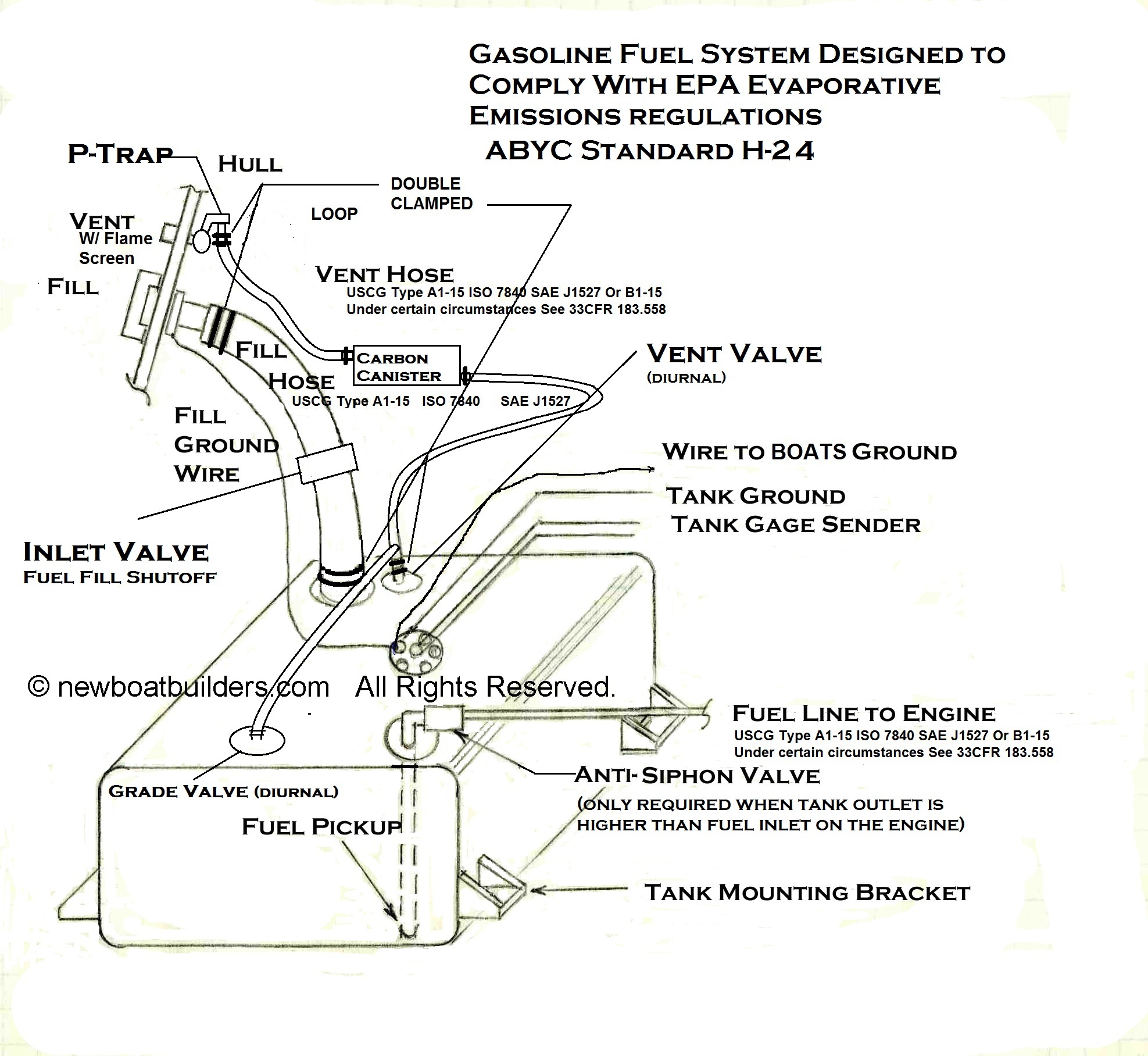
Moeller gauge wiring diagram 4 universal electric fuel sender instructions electric fuel. Retrofit procedure sending units retrofit procedure anti siphon valve.

Fuel Sending Wiring Diagram Gone Gain Seblock De
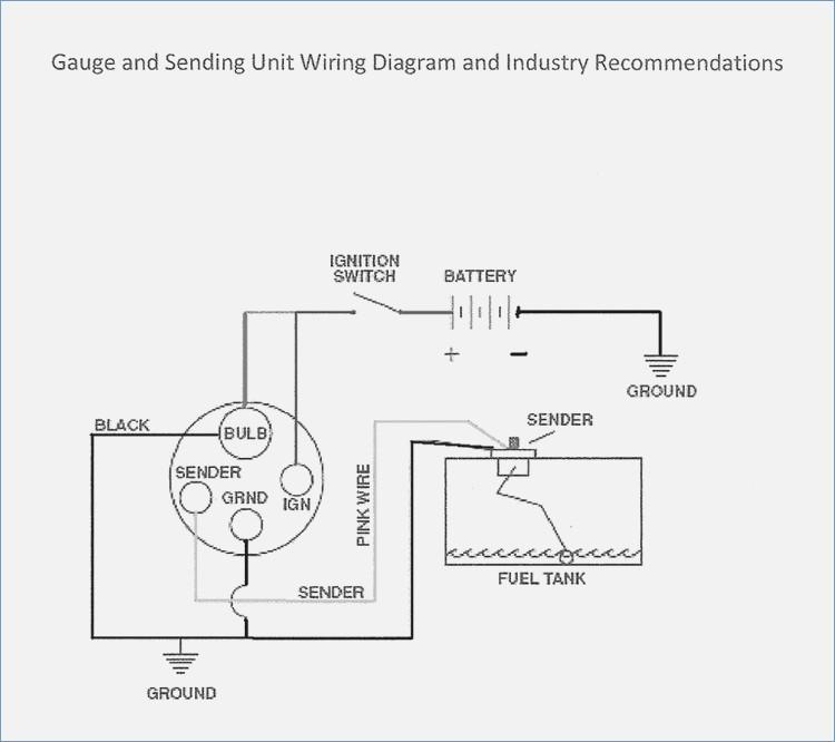
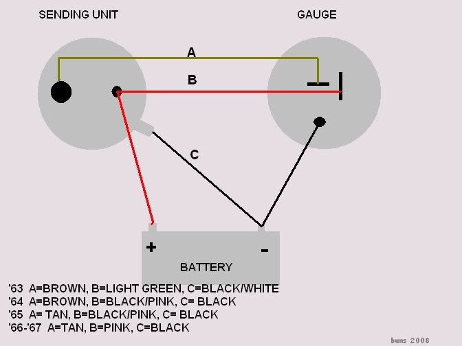
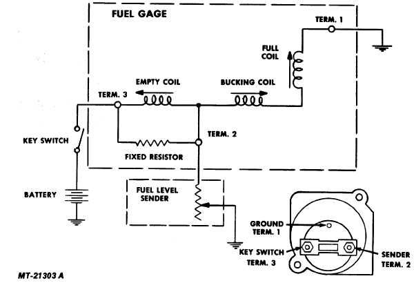
Moeller fuel gauge wiring diagram. To gauge fuel gauge sender to gauge igntion switch black bulb sender grnd sender battery ground fuel. Fuel gauge wiring diagram the moeller dash mount fuel gauge displays your boats fuel tank level in 14 tank increments. No diagram required if wiring is in compliance with tables i and il color yellow wred stripe yr yellow y dark gray gy brown br orange o purple pu. Need help to repair or retrofit the fittings on your moeller fuel tank. Fuel systems marine voltage i to g terminal 10 to 16 volts. Every piece has been pre inspected to guarantee full range of calibrated.
Moeller gauge wiring diagram 4 27 universal electric fuel sender instructions electric fuel sender installation guide fuel tank installation guide. Electric sending unit to fuel gauge wiring diagram your moeller promise. Microsoft word 0357271. The swingarm style measures fuel level the same way as the mechanical sending units but includes built in resistor and wiring to connect to a dash mounted gauge without requiring a. Fuel gauge wiring diagram moeller universal electric sending units are perfect for the diy converting a mechanical fuel gauge to an electrical dash mount gauge. Electric sending unit to fuel gauge wiring diagram your moeller promise.
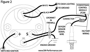
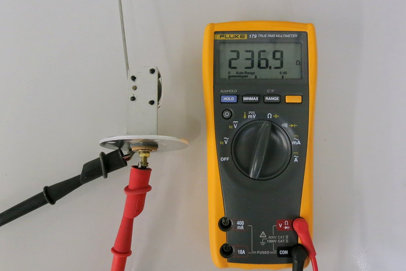
To test senders the resistance values are shown at minimum and full gauge scales. Every piece has been pre inspected to guarantee full range of calibrated readings and designed for gasoline applications. You can also use diesel if separate return line is available. Gauge pointer should be at the position shown in the lower portion of the diagram.
Gallery of Moeller Fuel Gauge Wiring Diagram
%2C445%2C291%2C400%2C400%2Carial%2C12%2C4%2C0%2C0%2C5_SCLZZZZZZZ_.jpg)